This thread has been locked.

If you have a related question, please click the "Ask a related question" button in the top right corner. The newly created question will be automatically linked to this question.

TPS54821: Regulator fails to start on a few parts in specific SS/TR Sequence

Part Number: TPS54821

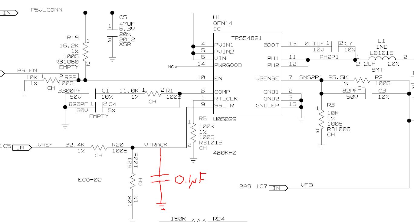
I am using the TPS54821 in a tracking mode.  In this case I have a 6A switching regulator design with a DAC that configures the SS/TR voltage.

On the input for SS/TR I have a resistor divisor and a parallel cap to do 2 things.

1.  Resistor divisor sets a range for the TR pin based on a 0 to 3.3V input.

2.  Capacitor smooth out the startup so the regulator doesn't over shoot the voltage it is tracking.  Using 0.01uF cap to slow the on time of VTRACK.


The problem I have run into is that I have a number of parts that fail to power on the regulator with a specific sequence.

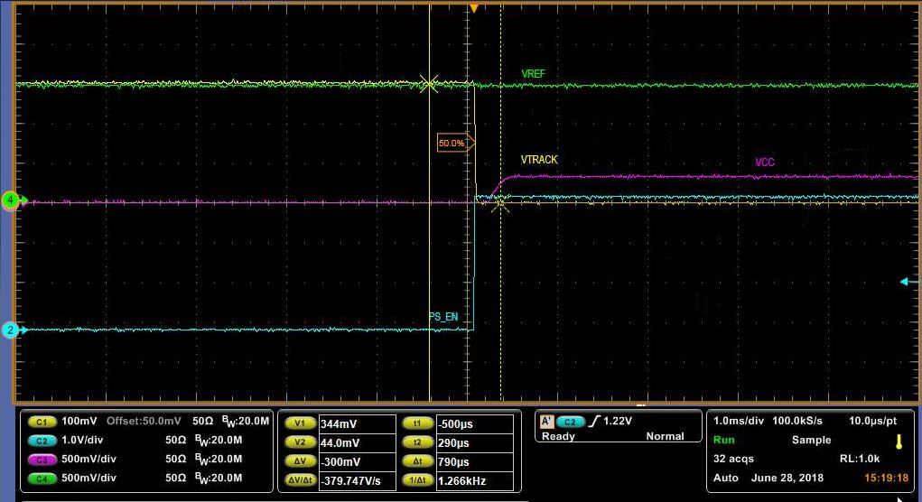
Sequence 1:  Apply 1.3V to VREF, then at a much later time, drive EN high. 

Sequence 2:  Apply 0.0 to VREF, drive enable high, then change VREF to 1.3V

Sequence 2 always works, across 200 parts.  Sequence 1, however, fails to work for a small sample of parts.   For the sequence 1 failure, I see a value of VTRACK held to basically 0.0V (I think measures about 30mV).  On the passing parts, I see VTRACK charge up once enable goes high. 

  • hello Gary,
    you mean sequence 2 is all right. sequency 1, some part couldn't power up, right?
    which point is VTRACK? you have noticed vtrack is zero when it happens failure. do you find the reason why it's zero?
    would you like to upload your schematic?

    Best regards,
    Edwin.
  • I cannot post the entire schematic, however I can answer a few of your questions.  I have updated a test to specifically test for this issue on a failing module.

    VTRACK is zero (well 44mV when the failure happens).  the only possible source of this is the TTPS54821.   I have captured the failure on a scope.  If you look at my VREF for the failing waveform, it maintains the same voltage before and after the power supply is enabled.  VTRACK is driven low (presumably by the TPS54821, since that is the only other item on this circuit.)

    Interestingly, I have another interesting data point..  This failure only occurs when VTRACK is above ~300mV when starting the regulator.  If VTRACK is below ~300mV then the regulator starts up properly.

    Passing waveform.  VTRACK at 292mV before PS_EN

    Failing waveform (same module, only change is the setpoint of VREF/VTRACK)

  •    Are my scope trace captures and partial schematic shown on my two posts?  They only show blank on mine.  Attaching them separately here.

  • Last note, in my quick drawing, I wrote 0.1uF next to the cap on VTRACK. The cap value is actually 0.01uF. This slows the rise of the VTRACK after enabling the supply avoiding a large overshoot before the regulator starts to use the VTRACK to regulate itself.
  • Hi,

    There are some dedicated and complicated control logics inside EN pin, which determine the behavior of external circuits. Glad you have these findings, however the logics are confidential and cannot be released publicly. We will update these on datasheet when necessary.
  • Iven,

    I was able to determine the symptom and the variables that affect this startup.

    With my original resistor divisor, 31.6K and 10K to create my VTRACK, the failure starts occurring when VTRACK is greater than ~300mV before the regulator is enabled (regulator starts when VTRACK is under 300mV).  If I use the same ratio and increase the current through my divisor (for the same voltage setting) the failure occurs at a lower VTRACK (regulator failed to start at VTRACK of 250mV).  So I then tested with a larger value resistor (lower current) of 63.4K and 10K and the failure goes away. (Regulator is able to start across my entire range of startup votlages)

    So it looks like this is a very specific failure related to the discharge of the SS/TR pin (something that appears to be done automatically when the regulator is enabled) and the amount of current that we are driving into the circuit.

    So my fix is to use larger value resistors to generate this reference.  It would be helpful to have more specific information on the value of resistors that can be used when using this regulator to track a voltage when it is expected that the enable can be driven high after the other regulator has already sequenced on.

    Gary Phelps