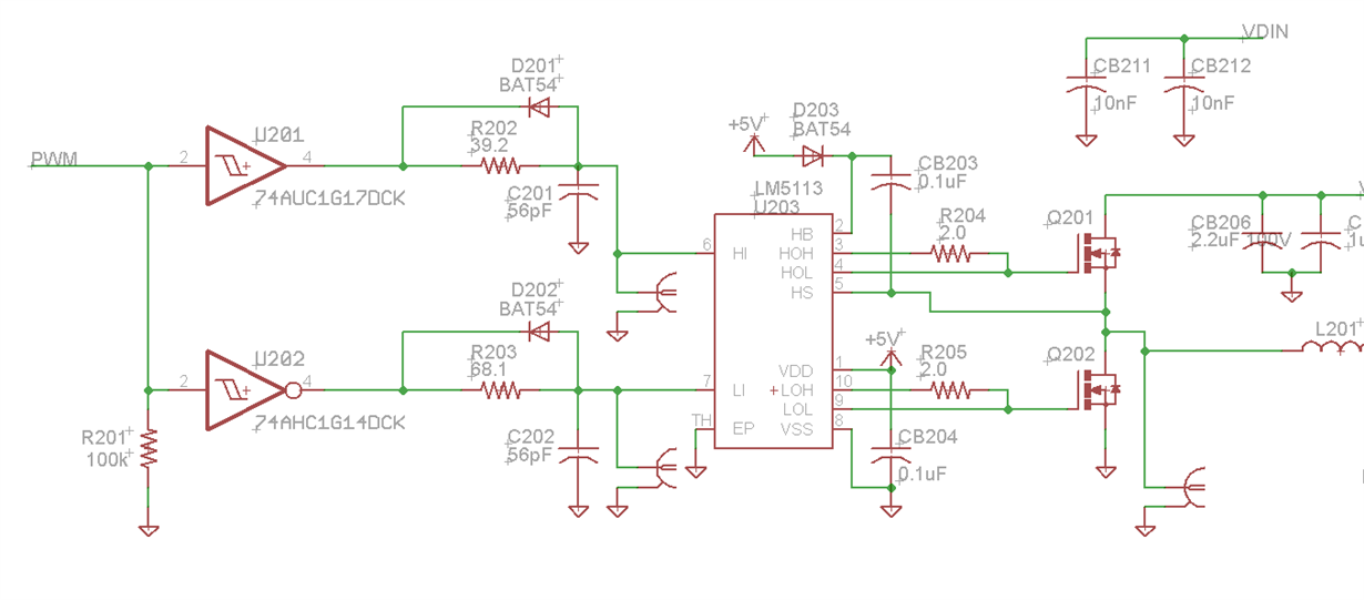
Hi all, I've observed this issue for a couple years now and hoped it would resolve itself, but it hasn't so I'm finally starting a discussion.
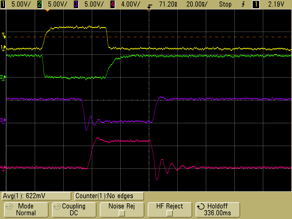
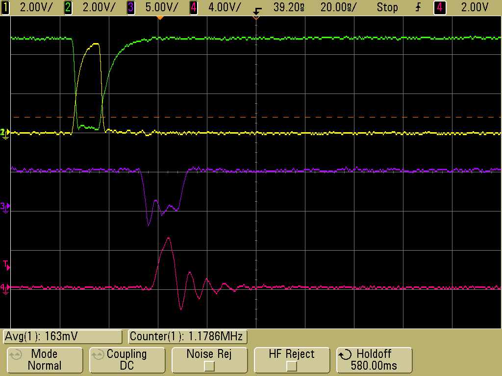
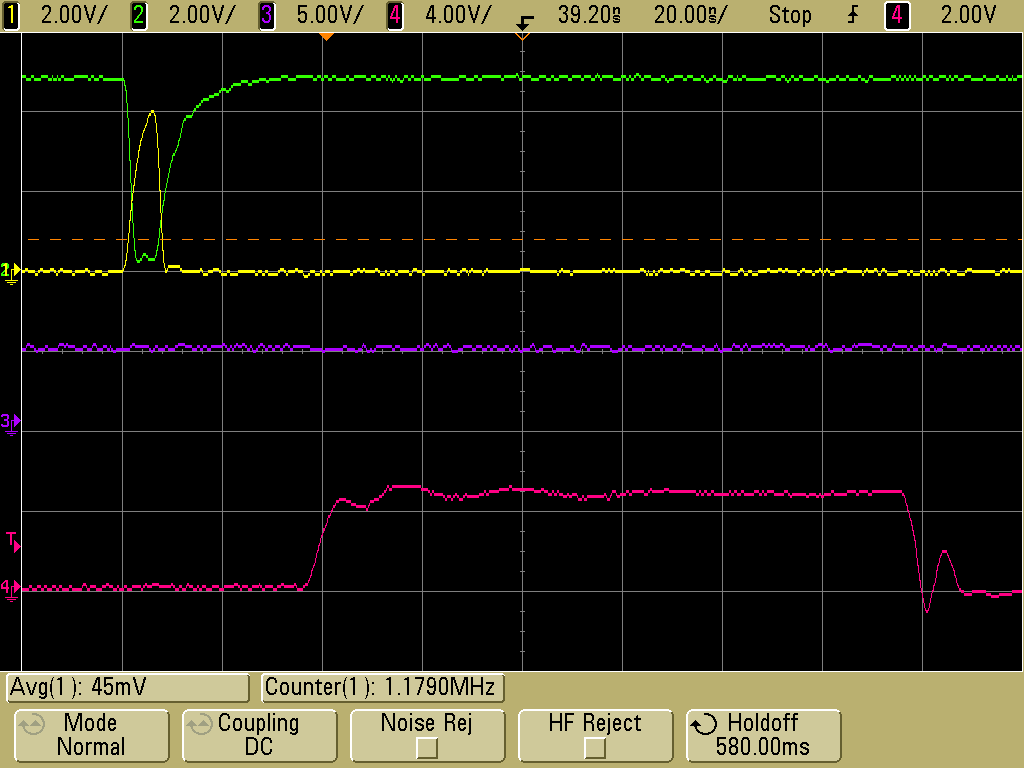
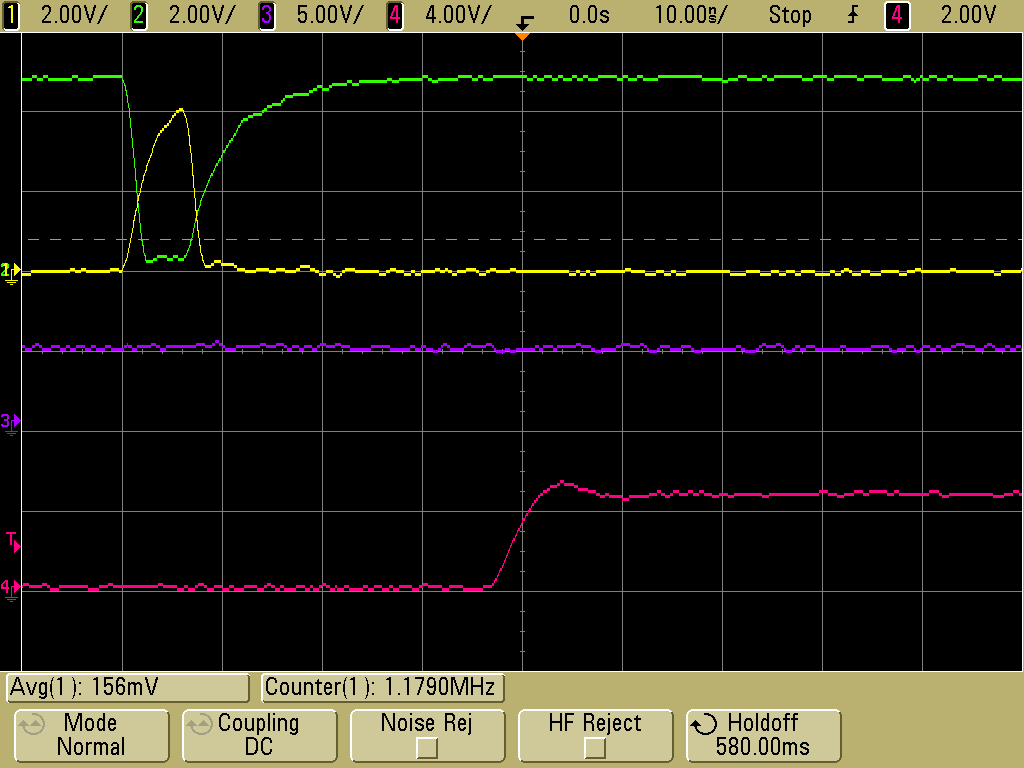
I've set up a synchronous buck converter using the LM5113 and a couple eGaN FETs with dead time circuits similar to those in EPC's development boards. This works well, except under specific conditions. If I slowly sweep my pulse width from around 50ns down to zero, I get a glitch on the HI output which causes severe cross conduction, and usually destruction of the device, if that pulse width is applied repeatedly. I've taken a few scope traces to demonstrate this. In all of them, CH1 (yellow) is the HI input, CH2 (green) is the LI input, CH3 (purple) is the HOL output, and CH4 (pink) is the LOL output. For this test, the DC bus for the buck converter is shorted to GND, as is the switch node (the HS pin), so as to prevent damage during the test.
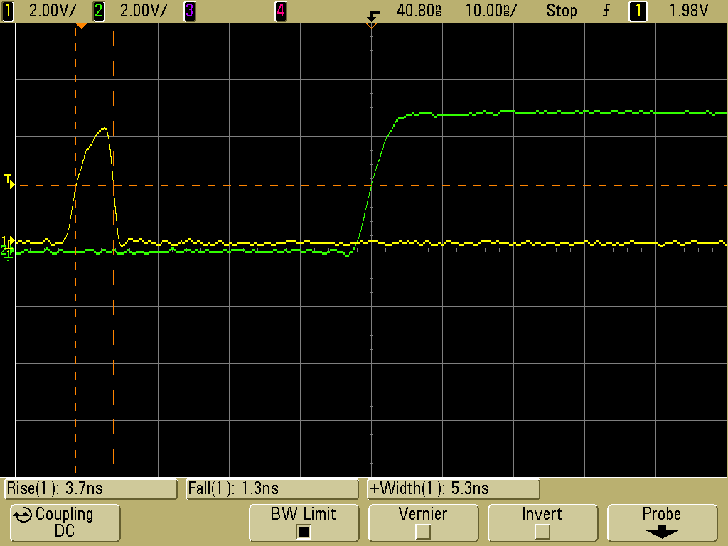
Here are my waveforms for a nice ~50ns input pulse. Outputs look good.
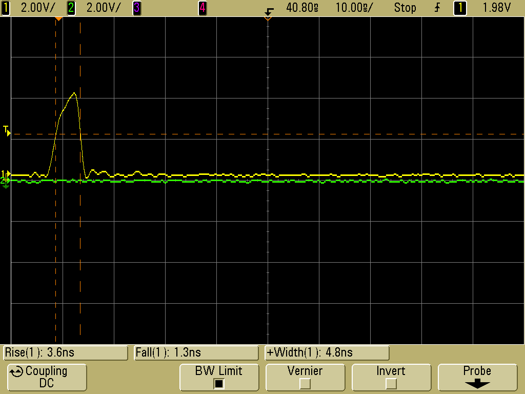
Here I my input pulse width is shortened to the point where the outputs barely keep up. Still no overlap to worry about.
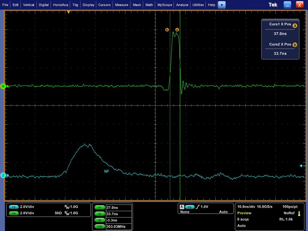
Now I shorten the input pulse even more an the glitch shows up. The lower gate drive stays high the entire time, while the upper gate drive gives a very long pulse. This is where the damage happens.
Here's another look at a glitch waveform, zoomed in a bit more.
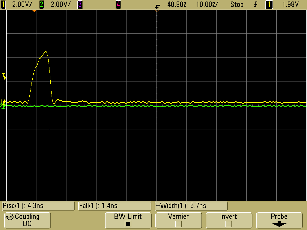
If I turn down the pulse width a little more, the glitch disappears entirely. Its duration always seems to be in the range of 30-150ns.
I've had this problem appear with both the WSON and DSBGA packages, and with different applied dead times, and I can always get it to manifest when I look for it. I can't find any alternative explanation than a silicon bug, but it would be great to have a fix for this. As it is, I have to implement a minimum pulse with in my PWM controller in order to avoid disaster. Most PWM chips don't have such a feature (at least not down to 10ns), so this is a real challenge for me.
Regards,
-Mike


