This thread has been locked.

If you have a related question, please click the "Ask a related question" button in the top right corner. The newly created question will be automatically linked to this question.

LLC resonant converter - Checking tank current waveform

Hi all,
I've been designing a full-bridge LLC resonant converter which is already constructed and in test. It almost works fine, but I detected an anomaly which I don't recognize.

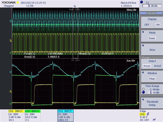
Looking at the current waveform through the ressonant tank, I get a step approximately 0.5us after the mosfet turn-on. It can be seen in both sides of the waveform, although it's more significant during the incrementing slope.

The specifications of the power supply are:

  • Power: 1.5kW
  • Vin_nom: 400V
  • Vout_nom: 48V(31A)-60V(25A)
  • Freq. range: 140kHz - 200kHz (resonant freq. 200kHz)
  • Center tapped transformer
  • Synchronous rectification (by now, internal diodes are working as rectifiers)

In the image of the oscilloscope attached, the conditions are:

  • Vin=200V
  • Rload = 30ohm (light load)
  • Fsw = 150kHz

Blue: tank current (to get the real value, must divide by 2)

Yellow: low-side mosfet gate signal

Green: Vdrain_source of the same low-side mosfet (oscilloscope scale not adequate)

When working at this condition, things work well although there appears this current step. But when increasing the input voltage (with same frequency) mosfets get burnt near 300V. When it works near the resonant frequency (200kHz), it works perfectly.

Can this step in the current waveform create any condition that makes the mosfets burn? What can generate this current step?

I've thought it could be the capacitance charge/discharge before the proper anti-parallel diode starts to conduct at the secondary. But I'm not sure of that.

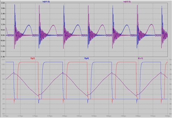
I made some simulations with real models from the manufacturer, which I also attached. It can be seen that the rectifiers start conducting approximately 0.5us after the proper mosfet turns on at the primary. Can the step in the current correspond to that instant?

I hope you can help me. Many thanks,

Alex S.

  • Please, any idea for the previous problem?

    Thanks,

    Alex S.

  • Hi Alex,


    I think the steps you are refering to are normal, they are from the transitions of the switches.  I am going to try to post

    a couple of scope photos I have of my Full bridge LLC.  The first one is at about 450W output and the second one is about 1000W output.


    Thanks

    Kevin

  • Sorry these didn't post the first time.

    Kevin

  • Sorry these didn't post the first time for some reason.


    If in fact these steps are what you are refering to, I think your problem may be something else.

    Thanks,

    Kevin

  • Hi Kevin,

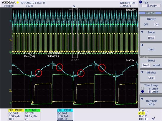
    I supose you are talking about the right steps, but to be sure, I attach the same plot with the steps I refer to in a red circle.

    As you can see, the steps appear some time after the transition (turn-on) of the mosfet (yellow waveform). This shift in time is what I do not understand.

    Many thanks! I'll wait for your plots.

    Alex

  • Hi Alex,

    For some reason none of my photos are posting.  But the steps you are refering too are not the ones I thought

    you were talking about.  I haven't seen those steps before in any of my LLC designs.

    Kevin

  • OK Kevin, thanks anyway!

    As I haven't seen it in any paper/application note and suposing it's caused by the secondary rectification (by the anti-parallel diodes of the synchronous rectifiers), I'm going to try to use dual fast-recovery diods. Fortunately, I prepared the footprints on the PCB to make this change.

    I'll write something after changing that.

    Again, thanks for your opinion,

    Alex

  • Hi again,


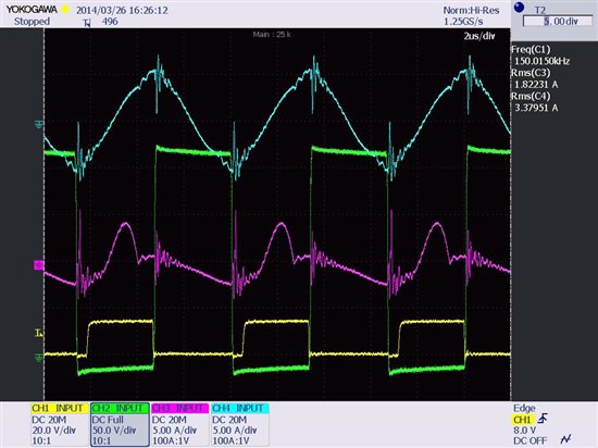
    I've already tried the rectification with diodes and it seems it works a bit better. In this case, as can be seen in the oscilloscope plot, the current step sawn before isn't there, so I can be quite sure it was from the synchronous rectifier with mosfets (at the previous plots, only the rectification was made with the anti-parallel diode, without turning on the mosfets).

    After changing the mosfets to diodes, I realised I didn't have a pull-down resistor from gate-source and, if the synchronous rectifier controller enable pin is disabled, the outputs are in high-impedance. I supose the mosfets weren't trully turned-off causing some disturbances or malfunction.

    But I solve a problem and find another! The purple waveform is the current through the rectifier diode (the real value is half the one showed on the oscilloscope screen). I sense it with a current probe. How can it be negative??! It is the current through a diode so, am I loosing something?! Remember I have a center-tapped transformer with the center-tap as positive output voltage.

    Kevin, did you find this while checking the rectified current?

    Hope you can give me any advice,

    Alex

  • Well, I finally got the answer. From my point of view, it may be occurring due to the current sensor, which is a high-frequency Rogowski. When I increase the load, this effect is less visible. According to the frequency band-pass of the Rogowski and appearing the problem when the current should be constant-zero, the issiue would be comming from this.

    Thanks a lot to all who have seen thes post and tried to help,


    Alex