This thread has been locked.

If you have a related question, please click the "Ask a related question" button in the top right corner. The newly created question will be automatically linked to this question.

UCC28061: UCC29061 Rogue Gate Drive Pulse Unit runs in Phase and Jumps out to Sync mode and then back to Phase mode ?

Part Number: UCC28061

This is being reposted to include the Schematic and Signal Waveforms -----Third Try's a Charm.

Gentlemen-

Expected the UCC28061 PFC controller to run in the "Phase" interleaved mode to reduce capacitor filter ripple current.

Looking for an explanation for "rogue' gate drive pulses using the UCC28061 interleaved PFC boost controller.  After the unit has started and is running into a constant current 500W DC output load we find the controller gate drives have a single "pulse" that randomly appears.  The circuit has been running in a "phase" mode and then appears to change over to a "synchronous" mode for a single cycle. It then quickly reverts back to "phase shifted" mode operation.  The load is fixed and the AC input line is set at 100 Vac.

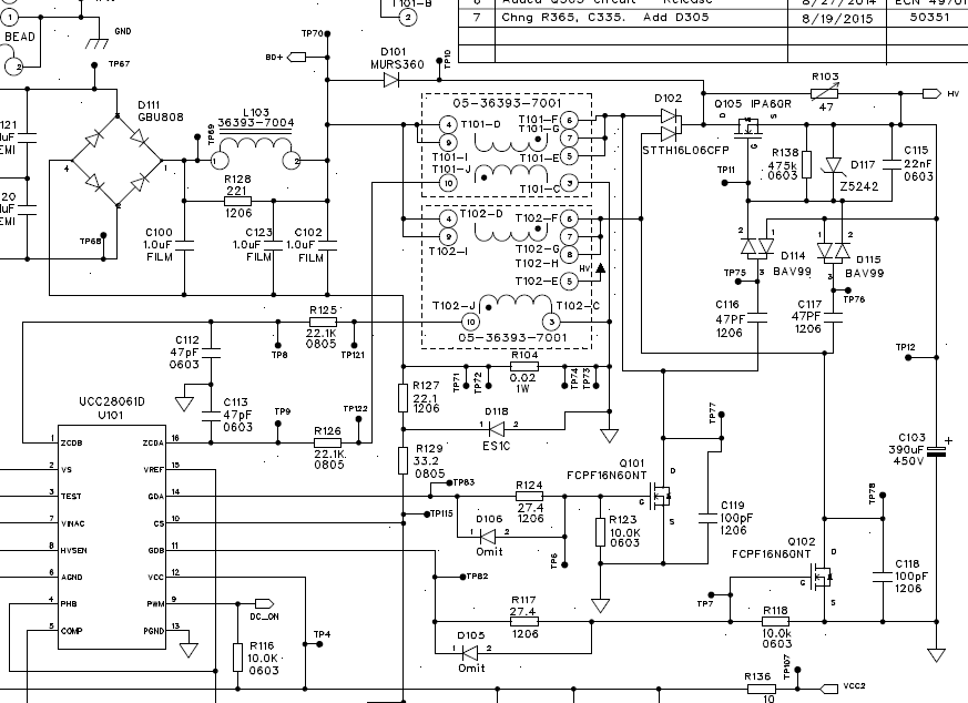
Circuit Schematic Reference:

O-Scope Trace     Phase - Sync- and back to Phase mode:


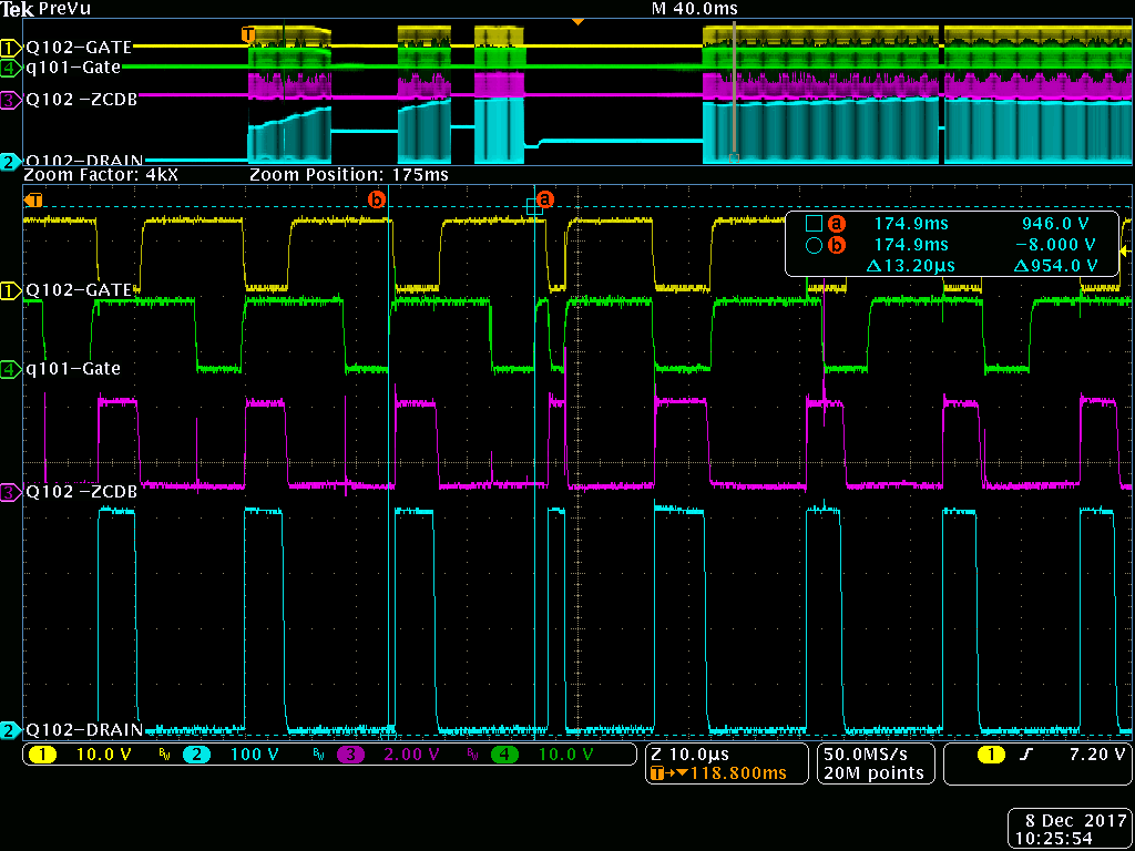
The top yellow trace is the boost Fet Q102 gate drive and the green channel is Q101 Fet gate drive. The two are in a phase mode most of the time.  Towards the center of sweep the "green" trace  Fet Q101 gate drive adds a "short pulse" and the next cycle becomes a "synchronous" event for both Fet's Q101 and Q102.  The following drive cycle you see it has transitioned back in to a "phased " gate drive sequence.

Our functional expectation was the controller would transition into a stable "Phase" mode operation and only change if an over current drive cycles are detected..  Is this correct ?

What may cause the controller to randomly inject a "short " gate drive cycle as seen above ? Outside of the over current detection fault is there another way for it to transition in and out of the "phase" mode ?

Thanks-

John

  • Hi John,

    Thanks for your interest in UCC28061. Are you seeing the random short pulse across all line and load conditions? Do you see the PWMCNTRL pin transition high at any point during operation? Do you only see the short pulse in GDA or does it appear in both GDA and GDB?

    Best Regards,
    Ben Lough
  • Hello Ben-

    Had a little problem attaching the schematic and the O-scope shot. Had to attach then as files to get then to go
    Cut and paste would not work on my system-

    Q- Are you seeing the random short pulse across all line and load conditions?
    A - Occurs at lower AC line voltages 90 - 120 Vac.
    Decreasing the output load also reduces the apparent number of short pulses on Q101 / GDA drive output only.

    Q - Do you see the PWMCNTRL pin transition high at any point during operation?
    A - PWNCTRL transitions from a high during start up and stays LOW at all other times.

    Q - Do you only see the short pulse in GDA or does it appear in both GDA and GDB?
    A - only on the GDA driver pin into Q101.

    John
  • Hello John,

    In answer to your question about when GDA and GDB are not 180 degs out of phase there are 4 conditions:

    1. An overcurrent
    2. Startup
    3. Loss of a ZCD signal.
    4. When PHB is re-enabled after a transition from single phase to dual phase (interleaved) operation

    In fact all of these conditions relate to loss of a ZCD signal. The UCC28061 uses a phase locked loop to maintain the 180 deg phasing relationship between GDA and GDB and it continually adjusts the on times to maintain correct timing.

    I think in your application GDA is the phase with the spurious signal. Please look at ZCDA and see what is happening there.
    There looks like there is a lot of noise everywhere and that may be a problem. But it could also be just noise pickup on your scope probes so try to see if this noise is real.

    It is important that the caps on ZCDA and ZCDB be connected to AGND and also TSET be connected to AGND. The PGND pin is connected to the source of the FETs and AGND is connected to the overcurrent resistor. I would review your layout and see if there is any room for improvement here.

    Regards

    John