This thread has been locked.

If you have a related question, please click the "Ask a related question" button in the top right corner. The newly created question will be automatically linked to this question.

UCC28910: Non isolated implementation: PMP 4443

Part Number: UCC28910
Other Parts Discussed in Thread: PMP, UCC28881

Hi,

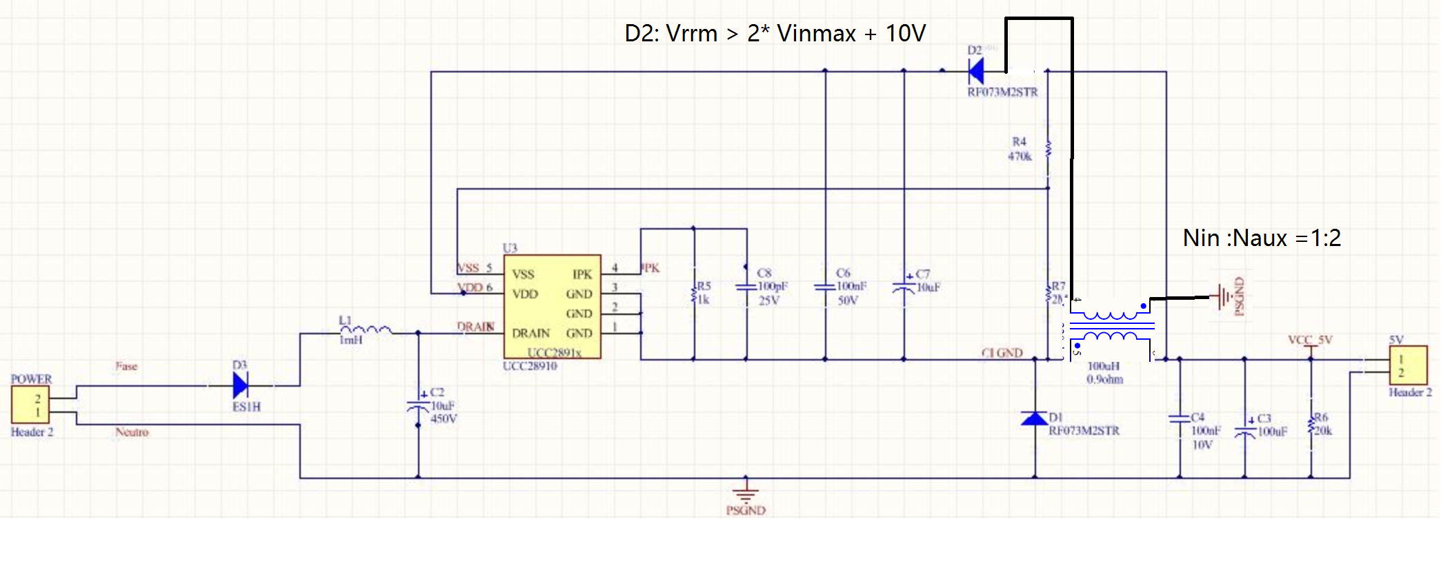
It is my first SMPS implementation. Im using UCC28910 to implement a 5V/200mA non isolated power supply based in http://www.ti.com/tool/PMP4443 and http://www.ti.com/lit/an/snva750/snva750.pdf.


I attached some waveforms to show my issue.

7245.Pictures.zip


I can see in my waveform that VS pin voltage is higher than recomended (4.6V) and my resistor divider on VS pin is not working. I can see my output in VS pin.

This is my problem?

Regards

Adelson
  • Hi Adelson,

    Thanks for your interest in TI's product.

    Can you share more information of your design specifications and test conditions , Such as input range , your target Brown in/out voltage ?

    And thank you captured so many waveforms , can you note the test conditions such as what is the input voltage and load condition.
    Take the first waveform for example . : 1). what mean of DC ? DC coupling?
    2), Please mark the maximum and minimum of voltage of VS --- add measurement
    3). if you capture the switching waveform , mark the frequency .
    4) If you have more probe , you can capture more than two channel in same waveform
    Such as VDD and Vdrain

    You can try to decrease the divider resistors on VS pin , 470Kohm means brown-in voltage is 98.7Vdc.

    Thanks.
  • Hi Jaden,

    Thanks for your reply.

    So, my brown-in voltage is approximately 100Vdc. i didnt understand very well what is this voltage, in PMP 4443 is not explicity (or i did not understand) what it is.

    My brown-out voltage is approximately 40Vdc.

    I need an output 5V @ 200mA

    about your questions:

    1) Yes, DC means DC coupling.

    2) 3) 4) i will do it in the next waveforms, thanks for hint!

    I did some tests days ago changing the value of R4 and R7 and the system started to work. I found the limit that R4 = R7 give output approximately 8Vdc/150mA and i cant below this voltage (5V for my application).

     when i use R7> R4 the power supply doesnt work, the VDD voltage goes to 10Vdc and the restart in 5Vdc. I think that the output voltage is responsible for VDD supply, isnt?

    Is there any way to get 5V?

    Regards,

    Adelson

  • Hi Adelson,

    Brown-in voltage means until the input voltage exceed this voltage , The controller IC will start to operation ,similar to UVLO.
    That is why I asked you what is your input voltage when you testing.


    R4 will decide the start-up voltage : V brown-in = Ivsl(run) * R4. Where Ivsl(run)=215uA,
    R4 and R7 will decide the output regulation voltage : Vo =Vvsr *(R4+R7)/R7 , where Vvsr = 4.05V

    So if you set up R4=R7 , the Vout should be 8.1V , that is make sense.

    you can try R4 = 234Kohm , R7= 1M , the Brown-in voltage is 50V , and Vo is 5V.


    Thanks.
  • Hi Adelson,

    I Ignored that the VDD were supplied by Vout , you are right .
    That is means VDD always hiccup due to Vout was lower than VDD_turn_off . too late in my time .

    Tomorrow I will check if other solution for you.
    Thanks.
  •  Hi Adelson,

    Please refer to above schematic , can you add a auxiliary  winding for VDD ?

    And we have another controller IC named UCC28881 which can meet your requirement without a aux winding for your application .

    I attached the EVM board for your reference. www.ti.com/.../sluubb6a.pdf

    Thanks.UCC28881 EVM -13V-225mA.pdf