A related question is a question created from another question. When the related question is created, it will be automatically linked to the original question.
If you have a related question, please click the "Ask a related question" button in the top right corner. The newly created question will be automatically linked to this question.
Hello Hirotsugu,
I am an applications engineer supporting the UCC27714 device and will work to answer your questions.
Since the EVM has the bias supplies provided externally, it is important to follow the power up sequence.
For the soft start function of the UCC28950 to provide proper soft start of the power train, the VIN must be applied before the bias supplies for the control circuits.
If bias is supplies are applied before VIN, the soft start sequence would likely be over before the input voltage is applied and there would be no soft start for the power train.
Please confirm if this answers your question on the thread buttons.
Regards,
Richard Herring
There are two types of BIAS. When turning on the power supply in the order of VIN -> BIAS1 -> BIAS2, the EVM was broken. I understand that BIAS1 is the power supply of the controller, so I need to put it last, but will I also need the order of VIN and BIAS2? Is it broken if BIAS2 -> VIN -> BIAS1?
Hello Hirotsugu,
I reviewed the EVM schematics and find that Vbias is for the secondary side including the controller, and Vbias2 is for the primary side including the gate drivers.
Since the EVM guide recommends applying VIN before both Vbias and Vbias2 supplies, and the Vbias is for the controller I recommend the following sequence to ensure the controller can execute the soft start.
VIN - Vbias2 - Vbias.
You asked about BIAS2 - VIN - BIAS1. Since the guide recommends applying VIN first, I would use the sequence I recommend above: VIN - Vbias2 - Vbias.
Hello Hirotsugu,
I would recommend using the power sequence shown in the Users Guide for power down which is to power down the bias before the VIN. I do not know if power down of VIN first will cause failure of the board.
I have investigated this problem with Richard, and I can explain why there is actually a clear reason to drop VBIAS2 first.
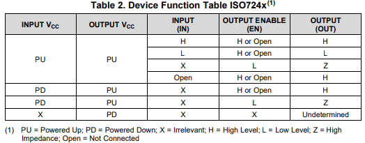
UCC27714 inputs are driven by an ISO7240M digital isolator. Please look at Table 2 in the ISO7240M datasheet. I have copied the table below.
If VBIAS (the input VCC,) is powered down, but VBIAS2 remains powered up, the output state defaults to high because the output enable pin (EN) is tied to the output supply pin. This will cause all inputs to both UCC27714 to become high. UCC27714 allows both HO and LO high simultaneously, and this can lead to shoot-through or damage to the EVM.
If VBIAS2 (the output VCC) is powered down, the UCC27714 devices will be deactivated correctly along with the ISO7240M. Current flow through the primary current sense transformer will be reduced to 0, and the controller CS pin voltage will decrease to 0V. The synchronous rectification from UCC27524A will be stopped by the UCC28950 once the voltage at the CS pin reduces below VDCM, as per Figure 47 of the UCC28950 datasheet. VDCM is approximately 0.39V.
To summarize: The correct sequence to power down should be VBIAS2 -> VBIAS -> VIN. Also, the correct sequence to power up should be VIN -> VBIAS -> VBIAS2, to avoid the same problem with ISO7240M output state defaulting to high.
As an additional precaution, I recommend installing a switch on the SS/EN pin to GND for the UCC28950. When the SS/EN pin is shorted to ground, the controller deactivates. By keeping the SS/EN pin shorted to ground until the correct sequence to power up has been completed, the controller will begin the soft start sequence only after the UCC27714 drivers are ready to receive inputs.
Thank you for bringing your issues with power sequencing to our attention. We will ensure that the user's guide is updated with this information.
The UCC28950 should soft start the output rail. There are two ways this can be achieved:
Short SS/EN pin to GND until all power sequencing is complete (Vin → Vbias → Vbias2). Release SS/EN short to GND to start the controller.
Replace the ISO7240M with a different digital isolator, such as ISO7640FM, that has default LOW output. Then, the power sequence becomes Vin → Vbias2 → Vbias. This does not require SS/EN pin to be shorted to ground, since Vbias is applied last. Furthermore, when using ISO7640FM or equivalent, Vbias may be removed first to disable the controller.
Thank you for your patience in working with this EVM. We are currently evaluating updates to the EVM, BOM, and user's guide to improve the ease of use, as a result of this E2E thread.