This thread has been locked.

If you have a related question, please click the "Ask a related question" button in the top right corner. The newly created question will be automatically linked to this question.

TPS65123 incorrect Output Voltages on VGH and VGL

Other Parts Discussed in Thread: TPS65123

Hi

I am having an issue with a TPS65123 design.  My output voltages have been configured for the following:

Vmain = 3V

VGH = 20V

VGL = -7V

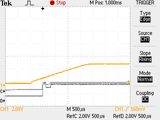
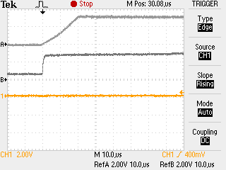
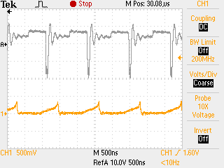
Vmain is coming up correctly.  However, VGH is reading 0V and VGL is reading +3.85V.  I re-configured Vmain to be 5V, and VGH and VGL to be +12V and -12V respectively.  No luck, VGH and VGL still reading the same as before.  Vmain has changed to 5V so that is still correct. 

Any help or ideas?

Thanks, Mike

  • Hi Mike,

    Can you tell me the resistor- values of VMAIN, VGH and VGL?

    Thanks,

    Ilona

  • Ilona

    VMAIN = 147K TOP, 100K BOT

    VGH = 1.54M TOP, 100K BOT

    VGL = 232K TOP, 100K BOT

    As mentioned previously, I re-configured to match one of TI's reference designs to see if it was a resistor issue.  I set VMAIN to 5V, VGL to -12V, and VGH to 12V, I changed all TOPs to 887K, VGL bottom to 365K, Vmain bottom to 287K, and VGH bottom stayed at 100k.

    See below circuit

     Thanks,

    Mike

  • Hi Mike,

    Try this: Pull R146 not to VMAIN but to VGH. Does that help?

    Regards,
    Ilona
  • Hi Ilona,

    No go.  I got the same thing on VGL and VGH when the bottom side of R146 was tied to VGH instead.  Also tried that tied to ground instead of Vmain or VGH, but that didn't show any results either. 

    Thanks

    Mike

  • Hi Mike,

    I am working on this.

    Regards,
    ilona
  • Ilona,

    Any update with this? I am having a similar issue with the same part.

    Thanks,
    David
  • Hi Mike,

    Did you record the start-up behavior of all outputs? Can you share a scope of VBOOT+VMAIN+VGH+VGL at the start-up ?
    Maybe the precharge phase (precharge BOOT cap to VIN) does not power up the device because of voltage drops on VIN. You have to consider the start-up sequence, first comes VMAIN then VGL and then VGH.

    Thanks,
    Best Regards,
    Ilona
  • In the first image above waveform A is VBOOT, B is VMAIN, C is VGH, D is VGL, and 1 is VIN.  The images are broken up so I apologize that the data has to be looked at in pieces.

    It looks like the power up sequence is going on before Vin is actually stable.  I am assuming I need to control the RUN and EN pins and toggle them once the power supply is stable?

  • Ilona could you please comment on the screen shots posted above?

    Thanks,
    Dave
  • Hi David, Hi Mike,

    I assume you both are working on the same schematic?!
    I am a bit confused how VGL (VGH) behaves. How is it possible that before even VIN starts VGL has already 500mV? Additionally there is no way that VGL can jump that fast up to ~VMAIN except the path via Resistances (R146+R147~340kOhm) and the output cap (100nF), which would charge VGL at a time constant of ~34ms. But in this case it jumps as fast as VMAIN <100us.
    Is VMAIN/VGL/VGH terminated with some load? If yes, does that start-up behavior appear when the load is not connected?

    The sequence is actually correct, VMAIN starts to ramp if EN=~1.21V, and in your case EN=VIN, which is ok. Same applies to VBOOT and the "Enable"-Pin RUN. Is it possible to zoom in at the ramp-area of VMAIN-VGL-VGH? How does the Switching- Node SWN behave, it might be helpful if you could at this plot as well.

    Thank you,
    Best Regards,
    Ilona
  • Ilona,

    Yes we are working off the same schematic.  I took some more images below.  Just as a note the previous images were taken with a TFT LCD attached while the ones below have no load at all.  There is a large operational difference in regards to VGH with and without the LCD attached.

    A = VMAIN

    B = VGL

    1 = VGH

    No load attached and all signals are triggered at power up of system

    A = SWN

    1 = SWP

    No load attached please note that both images were taken at different amplitude scales.

  • Hey guys,

    Ok let me check this in the lab.
    Regards
  • Hey,

    The only possibility when VGL can go positive is that the rectifier diode is mounted in the wrong direction (see scope), can you check if your diode is mounted correctly?

    Regards,

    Ilona

  • Ilona,

    Very helpful! That did the trick. The decal for the diode was incorrect as I thought a different part was installed that had a reversed polarity. Swapped the part around and the whole circuit worked perfectly. Thanks again for the help!
    Dave
  • Great to hear!
    Ilona