I am using the TLC59711 LED driver to drive four RGD LEDs with an Arduino Uno, and I am experiencing LEDs flashing off momentarily, and somewhat randomly, while receiving new grayscale levels over the built-in SPI protocol of Arduino (2 MHz). I purchased this kit from Adafruit.com, used their library for the TLC597111, and followed the tutorial found here: http://learn.adafruit.com/tlc5947-tlc59711-pwm-led-driver-breakout/overview
Alternatively, if I manually bit-bang the SPI channels (much slower at 70 kHz), there is no flickering observed. Running the unmodified example works fine, but if I change the Adafruit_TLC59711 constructor to use the built-in SPI function instead of bit-banging, the sketch still runs, but the LEDs will flash off periodically (for periods on the order of 1-10 ms).
-
//This constructor bit-bangs the SPI commands
//Adafruit_TLC59711 tlc = Adafruit_TLC59711(NUM_TLC59711, clock, data);

//This constructor uses the hardware SPI protocol, and causes LEDs to flicker.
Adafruit_TLC59711 tlc = Adafruit_TLC59711(NUM_TLC59711);
Can someone help me understand why using the built-in SPI causes flickering? I'd like to use the built-in SPI because it's much faster (2 MHz vs. 70 kHZ).
Thanks for any advice you can offer.
Setup:
- I have 4 RGB LEDs connected to the board.
- Current limit resistor is 1.98k, which is a 25mA limit.
- Connections below (followed Adafruit tutorial http://learn.adafruit.com/tlc5947-tlc59711-pwm-led-driver-breakout
- SDTI -> Arduino Digital 11 (MOSI)
- SCKI -> Arduino Digital 13 (SCK)
- VCC -> Arduino 3.3v
- GND -> Arduino GND
- VLED -> Arduino VIN (=4.1V)
- No connections on Arduino pins 10 and 12 (SS and MISO).
- SPI is communicating at 2 MHz (16 MHz clock divided by 8 )
- SPI mode 0 (default in SPI.cpp)
I scoped the SPI lines during a write and verified that the timing seems correct:
This is what it looks like with the stock example method, which is essentially bit-banging the SDTI and SCKI pins manually:
Note that the configuration register is defined as follows:
OUT_TMG = 1, EXT_GCK = 0, TMG_RST = 1, DSP_RPT = 1, BLANK = 0 --> 10110b
(see page 21 of the datasheet for more info about these register bits.)
As far as I can tell, whether the TLC59711's output is working properly without flickering, or the output is occasionally going low for one cycle, the hardware SPI transaction looks identical. That is to say, I verified that the grayscale data sent was correct, and the output from the TLC59711 was still 0. So I'm stumped.
Has anyone seen this before?
Here is a link to the datasheet http://www.ti.com/lit/ds/symlink/tlc59711.pdf.
The important data concerning communication protocol is on page 12 (SDTI and SCKI signals).
Code snippets:
TLC59711test.ino (Adafruit example sketch )
/***************************************************
  This is an example for our Adafruit 12-channel PWM/LED driver

  Pick one up today in the adafruit shop!
  ------> http://www.adafruit.com/products/

  These drivers uses SPI to communicate, 2 pins are required to
  interface: Data and Clock. The boards are chainable

  Adafruit invests time and resources providing this open source code,
  please support Adafruit and open-source hardware by purchasing
  products from Adafruit!

  Written by Limor Fried/Ladyada for Adafruit Industries.
  BSD license, all text above must be included in any redistribution
 ****************************************************/

#include "Adafruit_TLC59711.h"
#include <SPI.h>

// How many boards do you have chained?
#define NUM_TLC59711 1

#define data   11
#define clock  13

//Adafruit_TLC59711 tlc = Adafruit_TLC59711(NUM_TLC59711, clock, data);
Adafruit_TLC59711 tlc = Adafruit_TLC59711(NUM_TLC59711);

void setup() {
  Serial.begin(9600);

  Serial.println("TLC59711 test");
  pinMode(10, OUTPUT);
  tlc.begin();
  tlc.write();
}

void loop() {

  rainbowCycle(5);
}


// Slightly different, this makes the rainbow equally distributed throughout
void rainbowCycle(uint8_t wait) {
  uint32_t i, j;

  for(j=0; j<65535; j+=10) { // 1 cycle of all colors on wheel
    for(i=0; i < 4*NUM_TLC59711; i++) {
      Wheel(i, ((i * 65535 / (4*NUM_TLC59711)) + j) & 65535);
    }
    tlc.write();
    delay(wait);
  }
}

// Input a value 0 to 4095 to get a color value.
// The colours are a transition r - g - b - back to r.
void Wheel(uint8_t ledn, uint16_t WheelPos) {
  if(WheelPos < 21845) {
    tlc.setLED(ledn, 3*WheelPos, 65535 - 3*WheelPos, 0);
  } else if(WheelPos < 43690) {
    WheelPos -= 21845;
    tlc.setLED(ledn, 65535 - 3*WheelPos, 0, 3*WheelPos);
  } else {
    WheelPos -= 43690;
    tlc.setLED(ledn, 0, 3*WheelPos, 65535 - 3*WheelPos);
  }
}
Adafruit_TLC58711.cpp library
/***************************************************
  This is a library for our Adafruit 24-channel PWM/LED driver

  Pick one up today in the adafruit shop!
  ------> http://www.adafruit.com/products/1455

  These drivers uses SPI to communicate, 3 pins are required to
  interface: Data, Clock and Latch. The boards are chainable

  Adafruit invests time and resources providing this open source code,
  please support Adafruit and open-source hardware by purchasing
  products from Adafruit!

  Written by Limor Fried/Ladyada for Adafruit Industries.
  BSD license, all text above must be included in any redistribution
 ****************************************************/


#include <Adafruit_TLC59711.h>
#include <SPI.h>

Adafruit_TLC59711::Adafruit_TLC59711(uint8_t n, uint8_t c, uint8_t d) {
  numdrivers = n;
  _clk = c;
  _dat = d;

  BCr = BCg = BCb = 0x7F;

  pwmbuffer = (uint16_t *)calloc(2, 12*n);
}

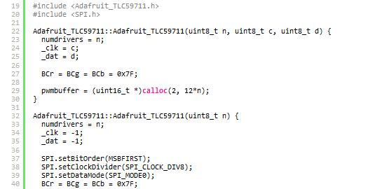
Adafruit_TLC59711::Adafruit_TLC59711(uint8_t n) {
  numdrivers = n;
  _clk = -1;
  _dat = -1;

  SPI.setBitOrder(MSBFIRST);
  SPI.setClockDivider(SPI_CLOCK_DIV8);
  SPI.setDataMode(SPI_MODE0);
  BCr = BCg = BCb = 0x7F;

  pwmbuffer = (uint16_t *)calloc(2, 12*n);
}

void  Adafruit_TLC59711::spiwriteMSB(uint32_t d) {

  // Bit-Banging method
  if (_clk >= 0) {
    uint32_t b = 0x80;
    //  b <<= (bits-1);
    for (; b!=0; b>>=1) {
      digitalWrite(_clk, LOW);
      if (d & b)
	digitalWrite(_dat, HIGH);
      else
	digitalWrite(_dat, LOW);
      digitalWrite(_clk, HIGH);
    }
  } else {
    // Arduino's hardware enabled SPI:
    SPI.transfer(d);
  }
}

void Adafruit_TLC59711::write(void) {
  uint32_t command;

  // Magic word for write
  command = 0x25;

  command <<= 5;
  //OUT_TMG = 1, EXT_GCK = 0, TMG_RST = 1, DSP_RPT = 1, BLANK = 0 -> 0x16
  //OUT_TMG = 1, EXT_GCK = 0, TMG_RST = 0, DSP_RPT = 1, BLANK = 0 -> 0x12
  //OUT_TMG = 0, EXT_GCK = 0, TMG_RST = 0, DSP_RPT = 1, BLANK = 0 -> 0x02
  command |= 0x16;

  command <<= 7;
  command |= BCb;

  command <<= 7;
  command |= BCg;

  command <<= 7;
  command |= BCb;

  cli();
  for (uint8_t n=0; n<numdrivers; n++) {
    spiwriteMSB(command >> 24);
    spiwriteMSB(command >> 16);
    spiwriteMSB(command >> 8);
    spiwriteMSB(command);

    // 12 channels per TLC59711
    for (int8_t c=11; c >= 0 ; c--) {
      // 16 bits per channel, send MSB first
      spiwriteMSB(pwmbuffer[n*12+c]>>8);
      spiwriteMSB(pwmbuffer[n*12+c]);
    }
  }

  if (_clk >= 0)
  {
    //digitalWrite(_dat, LOW);
    delayMicroseconds(200);
  }
  else
    delayMicroseconds(2);
  sei();
}


void Adafruit_TLC59711::setPWM(uint8_t chan, uint16_t pwm) {
  if (chan > 12*numdrivers) return;
  pwmbuffer[chan] = pwm;
}


void Adafruit_TLC59711::setLED(uint8_t lednum, uint16_t r, uint16_t g, uint16_t b) {
  setPWM(lednum*3, r);
  setPWM(lednum*3+1, g);
  setPWM(lednum*3+2, b);
}

void Adafruit_TLC59711::setLED(uint8_t lednum, uint16_t rgb[3]) {
  setPWM(lednum*3, rgb[0]);
  setPWM(lednum*3+1, rgb[1]);
  setPWM(lednum*3+2, rgb[2]);
}
boolean Adafruit_TLC59711::begin() {
  if (!pwmbuffer) return false;

  if (_clk >= 0) {
    pinMode(_clk, OUTPUT);
    pinMode(_dat, OUTPUT);
  } else {
    SPI.begin();
  }
  return true;
}
Arduino's SPI.cpp
/*
 * Copyright (c) 2010 by Cristian Maglie <c.maglie@bug.st>
 * SPI Master library for arduino.
 *
 * This file is free software; you can redistribute it and/or modify
 * it under the terms of either the GNU General Public License version 2
 * or the GNU Lesser General Public License version 2.1, both as
 * published by the Free Software Foundation.
 */

#include "pins_arduino.h"
#include "SPI.h"

SPIClass SPI;

void SPIClass::begin() {

  // Set SS to high so a connected chip will be "deselected" by default
  digitalWrite(SS, HIGH);

  // When the SS pin is set as OUTPUT, it can be used as
  // a general purpose output port (it doesn't influence
  // SPI operations).
  pinMode(SS, OUTPUT);

  // Warning: if the SS pin ever becomes a LOW INPUT then SPI
  // automatically switches to Slave, so the data direction of
  // the SS pin MUST be kept as OUTPUT.
  SPCR |= _BV(MSTR);
  SPCR |= _BV(SPE);

  // Set direction register for SCK and MOSI pin.
  // MISO pin automatically overrides to INPUT.
  // By doing this AFTER enabling SPI, we avoid accidentally
  // clocking in a single bit since the lines go directly
  // from "input" to SPI control.
  // http://code.google.com/p/arduino/issues/detail?id=888
  pinMode(SCK, OUTPUT);
  pinMode(MOSI, OUTPUT);
}


void SPIClass::end() {
  SPCR &= ~_BV(SPE);
}

void SPIClass::setBitOrder(uint8_t bitOrder)
{
  if(bitOrder == LSBFIRST) {
    SPCR |= _BV(DORD);
  } else {
    SPCR &= ~(_BV(DORD));
  }
}

void SPIClass::setDataMode(uint8_t mode)
{
  SPCR = (SPCR & ~SPI_MODE_MASK) | mode;
}

void SPIClass::setClockDivider(uint8_t rate)
{
  SPCR = (SPCR & ~SPI_CLOCK_MASK) | (rate & SPI_CLOCK_MASK);
  SPSR = (SPSR & ~SPI_2XCLOCK_MASK) | ((rate >> 2) & SPI_2XCLOCK_MASK);
}
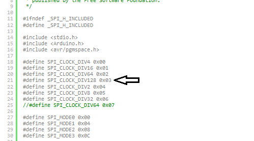
Arduino's SPI.h
/*
 * Copyright (c) 2010 by Cristian Maglie <c.maglie@bug.st>
 * SPI Master library for arduino.
 *
 * This file is free software; you can redistribute it and/or modify
 * it under the terms of either the GNU General Public License version 2
 * or the GNU Lesser General Public License version 2.1, both as
 * published by the Free Software Foundation.
 */

#ifndef _SPI_H_INCLUDED
#define _SPI_H_INCLUDED

#include <stdio.h>
#include <Arduino.h>
#include <avr/pgmspace.h>

#define SPI_CLOCK_DIV4 0x00
#define SPI_CLOCK_DIV16 0x01
#define SPI_CLOCK_DIV64 0x02
#define SPI_CLOCK_DIV128 0x03
#define SPI_CLOCK_DIV2 0x04
#define SPI_CLOCK_DIV8 0x05
#define SPI_CLOCK_DIV32 0x06
//#define SPI_CLOCK_DIV64 0x07

#define SPI_MODE0 0x00
#define SPI_MODE1 0x04
#define SPI_MODE2 0x08
#define SPI_MODE3 0x0C

#define SPI_MODE_MASK 0x0C  // CPOL = bit 3, CPHA = bit 2 on SPCR
#define SPI_CLOCK_MASK 0x03  // SPR1 = bit 1, SPR0 = bit 0 on SPCR
#define SPI_2XCLOCK_MASK 0x01  // SPI2X = bit 0 on SPSR

class SPIClass {
public:
  inline static byte transfer(byte _data);

  // SPI Configuration methods

  inline static void attachInterrupt();
  inline static void detachInterrupt(); // Default

  static void begin(); // Default
  static void end();

  static void setBitOrder(uint8_t);
  static void setDataMode(uint8_t);
  static void setClockDivider(uint8_t);
};

extern SPIClass SPI;

byte SPIClass::transfer(byte _data) {
  SPDR = _data;
  while (!(SPSR & _BV(SPIF)))
    ;
  return SPDR;
}

void SPIClass::attachInterrupt() {
  SPCR |= _BV(SPIE);
}

void SPIClass::detachInterrupt() {
  SPCR &= ~_BV(SPIE);
}

#endif


