This thread has been locked.

If you have a related question, please click the "Ask a related question" button in the top right corner. The newly created question will be automatically linked to this question.

TLC59116: LEDs not turning on

Part Number: TLC59116
Other Parts Discussed in Thread: OPT3001

Hi,

we have a simple board with only 2 x TLC59116 on the I2C but. One with HW address selecting bits to 0 and the second to 1.

I send the code below (only few lines in main() but the LED does not turn on. The I2C communication on the scope is correct, I see all 3 bytes including the ACK for each byte so the device is receiving the data.

Can you please let me know:

- am I missing something

- do I need to run some other commands before or after in order to turn the LEDs on?

- can you please write a snipped of pseudo-code with the correct bytes/commands sequence 

Many thanks

Rick

        //compose message
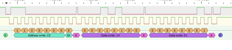
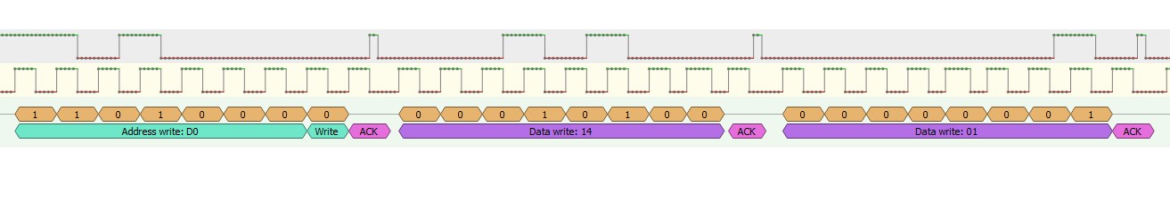
        i2cData[0] = 0xC0;  // I2C slave address (including A0 HW-configured) + R/_W bit
        i2cData[1] = 0x14;  // Control register
        i2cData[2] = 0x01;  // Set LED fully on
        i2cDataSz = 3;      // message size

        I2CState = I2C_SendMessage(I2C_2, i2cData, i2cDataSz);

  • Hi, Rick,

    Please try using the allcall address 0x68 to test if the address is correct.

    Here I attach our code for your reference.

    5086.TLC59116 Sample Code.zip

    Please let me know if this solves your problem.

    Thanks.

    Regards,

    Kenneth

  • Thank you Kenneth,

    nothing happened when I sent 0x68. LEDs still didn't turn on.

    Thank you for the code, there are functions which are not defined so I cannot see what they do. It looks like they are part of the library. So for example I2C_masterSendMultiByteStart has 2 parameters but I cannot see its implementation.

    For that reason and also because I see the I2C comms working correctly I was initially asking for a detailed pseudo code to get to even just turn a single LED on.

    Could you please do that. Including any codes to be sent for even the most basic setup/configuraiton which might required before trying to switch any LED on.

    Because we need to sort this out asap because of a trade show which is in a week time and with the weekend coming up we have to sort this asap. Could I also ask you to kindly keep an eye out for any updates I might post just in case.

    Many thanks in advance :)

    Best regards
    Rick

  • Hi Kenneth,

    today has passed with no reply to my post and this is now extremely urgent, can you please reply asap (very kindly asked!! :) ) to my post to your message yesterday.

    I tried the 0x68 and it does not work either. 

    Please see attached waveform of the protocol analyser showing both 0x68 (0xD0 shifted) AND 0xC0 (0x60 shifted).

    As you can see the communication is working so no issues there, the IC sends ACK tot he full message. It is just a matter of knowing the exact sequence of commands/data to write to a fresh IC from the production line to get it up and running. Which is all I was asking in the first place, just a pseudo code list of codes and operations to get to the first LED to turn on, after that I can work all the rest out myself.

    I assume you are quite busy too so to save you (and me) time and avoid going back and forth could you please answer each of the following questions both separately and in detail:

    1. Most important one... as asked in my original post could you please write in pseudo code all (i.e. each and every value written to the I2C port to get it from first time boot from PCB manufacturing (i.e. totally fresh chip) to turning an LED on. 

    2. can you please check again my original post with the code. That is the ONLY code in the main and the IC has not been programmed ever before. Is that ALL that is needed to turn the LED on or is there some other setup required before or after? Are there some modes to configure first perhaps??

    3. after trying to make sense of that code for hours I found out at the top that it is for the OPT3001. Did you send the wrong code?

    4. there is no source code for most of the I2C functions so I have no idea what they do exactly. Same for the #defines (they are missing) for the values passed to the functions so again I cannot debug what they are passing. Can you please send me the full code/files.

    Many thanks again! :)

    Rick

  • Hi, Rick,

    The code is correct and it's written based on a former code so some info may not remove.

    Anyway, let me give you the full steps for achieving this by using Allcall address for a quick check and you can also get it through the datasheet:
    1. Send MODE1 (Addr = 00h) with data 01h to select All Call address;
    2. Send MODE2 (Addr = 01h) with 00h;
    3. Send Addr = 02h to Addr = 11h with FFh to set PWM0-PWM15;
    4. Set Addr = 12h for FFh to set GRPPWM;
    5. Set Addr = 13h for 3Fh, just for example;
    6. Set Addr = 14h to Addr = 17h to FFh;
    7. Set Addr = 1Ch to F8h.

    This should turn on all your LEDs.

    Let me know your feedback.

    Kenneth
  • Thank you Kenneth,

    Now it seems to work. :)

    The only thing is that it works only if I call it with 0x60 address and not with the All Call. I am not clear as to how the All Call works. I tried googling it and also looked in details in the datasheet but can only find a brief unclear explanation as to how it works and how to set it up.

    Two questions:

    1. Can you please explain me how the all call works or where I can find a detailed explanation about it

    2. You mentioned those steps that you sent me are also mentioned in the datasheet. I could not see them. What page are they?

    Thank you again for you help! :)

  • Hi, Rick,

    All call address is also called broadcast address.

    The steps are not descriped, but the registers are mentioned and you can refer the function for how to configure them.

    If you think this answers your question, please help to click "Resolve".

    Thanks.
    Regards,
    Kenneth