A related question is a question created from another question. When the related question is created, it will be automatically linked to the original question.
If you have a related question, please click the "Ask a related question" button in the top right corner. The newly created question will be automatically linked to this question.
Existing posts in the forum comment that connecting the output of two LDOs ( linear regulators ) in parallel is not typically recommended. Current sharing can not be guaranteed. One of the existing posts points to an application note on how to connect LDOs in parallel using ballast resistors to force current sharing. http://www.ti.com/lit/an/slva250/slva250.pdf In general, it's always best to use a single LDO rated for the required output current.
Many thanks for this PDF. I've made couple configurations with LM2940 5V and ballast resistors.
I've read somewhere that those should be 0,1 - 1ohm rating. But non of these values work for me.
I have very specific project: Vin is from 5,5 to 21V , Current is up to 0,5A! On PCB are five LM2940 that should share this current (TO-252).
From the PDF calculations show me that resistors should have 27,7 ohm - do this might be correct???? (please recalculate this since I can do some mistake). I've made PCB with 24ohm, but the current decrees about 50%. I also could not figured out it LM2940 heat up evenly (my feeling were subjective - I don't have thermometer for this moment).
Ballast resistors are used to compensate for the very slight mis-match in output voltages between multiple parallel regulators.
The regulator with the highest output voltage, even if only a few millivolts, will always be providing a larger portion of the load current than the rest of the (lower output voltage) regulators.
With five in parallel, it's very possible that one of the regulators (the one with the lowest output voltage) will never share any current.
Hence, some (or perhaps one) of the regulators will be cooler than the others.
All in all, this is not a very efficient way to operate.
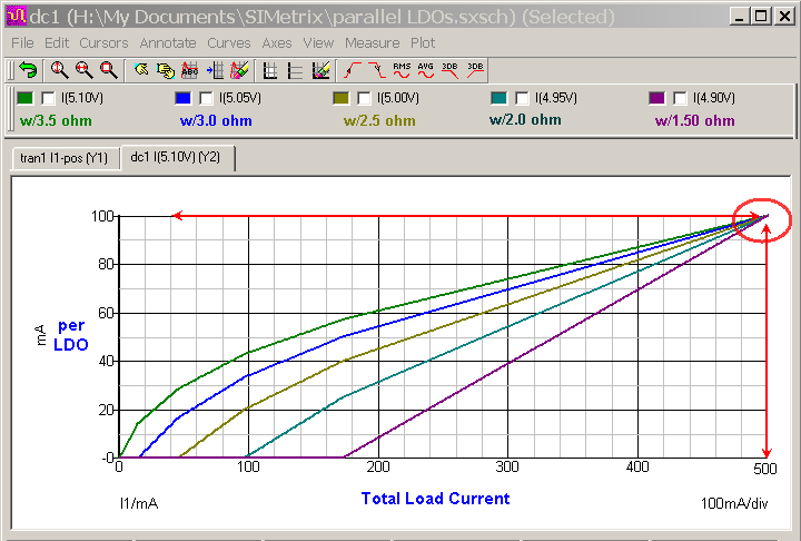
For example, if you have five random LM2940-5.0 devices with no load output voltages of 4.90V, 4.95V. 5.00V, 5.05V, and 5.10V (i.e. 5V +/-2%) and each output has a 1 Ohm series resistor for ballast, the intial load current would all be from the 5.10V output until there was enough IR loss across the ballast resistor to engage the next lowest output (5.05V).
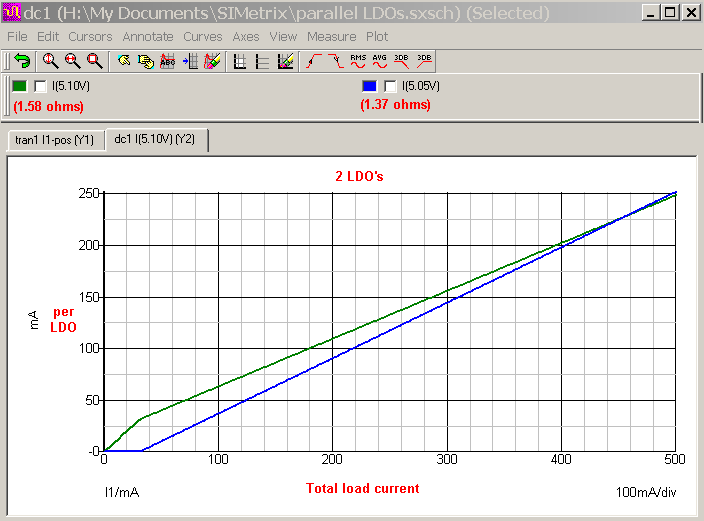
With the 5 output voltages listed above, and a 1 Ohm ballast resistor on each output, at 500 mA load current the individual regulators will supply as follows:
5.10V = 199.7mA (40%) ; 5.05V =149.8mA (30%) ; 5.00V= 100mA (20%) ; 4.95V = 50.1mA (10%) ; 4.90V = 0.3mA (~0%) ; with the voltage at the load = 4.89V
With the 5 output voltages listed above, and a 2 Ohm ballast resistor on each output, at 500 mA load current the individual regulators will supply as follows:
5.10V = 150mA (30%) ; 5.05V = 125mA (25%) ; 5.00V= 100mA (20%) ; 4.95V = 75mA (15%) ; 4.90V = 50mA (10%) ; with the voltage at the load = 4.79V
The secrect is to get very closely matched output voltages among the 5 regulators.
Aaaa, that was very very helpful answer. Now it makes sense for me.
Which formula did you calculate those % usage ?
It seems now that 27 ohm value for ballast will make % usage close to equal distribution of current.
On my final PCB I placed 0,1 ohm 1% resistors. That's why it makes first LM with the highest V output really hot.
Now. Correct me if I'm wrong. Lets say that on full load, on 21 input voltage and 0,5A current the LM with the highest % usage becomes very hot and reaches the temperature limit - in this case 125 deg C. Overheat protection starts to decrease current. Does the decreased load will be taken by other LMs that are cooler?
The PCB won't be often used with 21V input but Voltages like 13V or 16V yes. On 13V input the highest temperature noticed was 85 deg C.
Today I will make test with 21V input and checked the temperature - probably it will reach around 100-110 deg C.
Formula is not finalized yet, but will be soon (I hope) in an application note specifically written for this situation. Results that I gave here are from SPICE simulations.
Keep in mind that the Vout values that I used are just my convenient guess at some typical range of values. The reality will likely be different in some way.
OK, let's say 27 Ohms is your chosen ballast resistor value on each of the five outputs, all regulator outputs are at 5.00V, and the 500mA is evenly distributed so each regulator is providing 100mA ... the voltage at the the will load be somewhere around 5.00V - ((27 ohms/5) * 500mA) = 2.30V. Is that OK for you? My opinion is that it (2.30V) is a bit low if your load is expecting 5.00V.
This highlights the trade-offs involved when using ballast resistors with multiple LDO's. Using larger values can force close to ideal current sharing, but causes unrealistic voltage drops at the load. Using lower values can reduce the voltage drop at the load to acceptable values, but the load sharing between the regulators may not be well defined. You will need to determine the acceptable trade-offs for your application.
Personally, I'd say 5 ohms per output is just about as large as I would go. That would keep the load voltage to about 4.50V, give or take a few tens of milli-volts.
You might want to consider the use of a single SMPS buck regulator with the inherent higher efficiency. The trade off here is that for some small increase in circuit complexity the current sharing issue goes away.
If one device goes into thermal limiting will the others take up the load? Yes. For the National Semi version the thermal limiting temperature will be closer to a junction temperature (Tj) of 150 deg C, and I presume the TI versions will be very similar.
A temperature of 110 deg C, by itself, will not cause any significant change in operation, and is certainly not close to the thermal limiting temperature. There might be a slight change in output voltage(s) due to temperature, but all five LDOs should be at close to the same temperature if they are mounted close together (as they should be). Increasing copper area under the device tabs, using 2 ounce copper instead of 1 ounce, using multi layer boards with thermal via's, etc, can all help keep junction temperature down.
That would be correct. I've made a test with 27ohm resistors and the current drops by 50%. So that's not the way.
Therefore calculations from the PDF from the firsts post are just guide.
And therefore best way to figure out the best value is trial values and tests.
If that day I design the PCB I have knowledge like this day I wouldn't pick 0,1ohm as target value. To bad for me, I can not change it now.
Thus now I have to cope the thermal problems. That's why I ask those thermal limits of LM's.
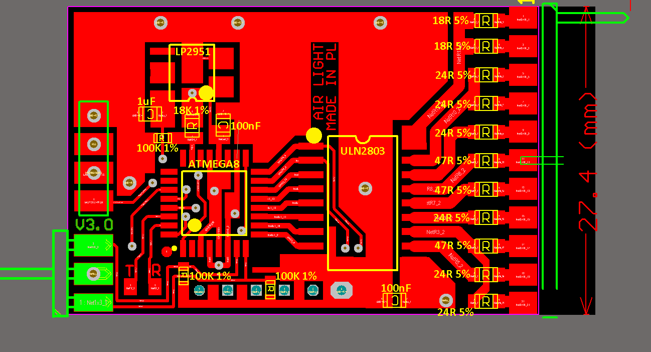
Yet, 5V is essential. Project drives LED lamps which works around 2,7 and 3,5V. But the LED are driven by ULN2803 which generate quite big voltage drop around 1-1,5V.
PCB is small. 40 x 27mm with TOP and BOTTOM layer. Cooper thickness is 70um. PCB thsickness is 2mm.
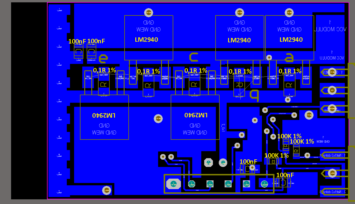
I have made as large poles as I could - LM's are TO252.
Please take a look. LM's are all on the BOTTOM side - blue image. During load test on all LM's were glued radiator - flat alu, 2mm thick (40x25mm).
On the TOP layer are micro controller and darlington driver, plus some RLC components.
When the stabilisers reaches 110 C deg (despite of radiator) those elements have aproxx. 80 C deg.
The load test shows that individual temperatures of LM's were from 80 to 110 C deg (therein two of them were 110 and 100-109)
Tomorrow I will try the same load test but with differ radiator with ribs to check if it could help to dissipate heat.
Unfortunately the major heat is transferred into the PCB since the TO252 is SMD mounting element.
About the other regulators. SMPS is not suitable - weight. The PCB needs to be light weight since it will be flying in RC planes in which weight is essential.
I tried with the Switchers. There is big disadvantage of this technology. It's very hard to overcome the EMI noise. It's doable but only under some conditions.
My project futures some sudden current consumptions (by LEDs) that generates problems for regulators to survey the consumption. Even with really big and fast capacitors. We are talking about 150mA peaks. It doesn't seems much yet.
Those EMI interference with RC receivers which above project is designed for and work with.
I have tried to power the PCB with brand mark switcher for RC branch with 3A efficiency - it didn't make it.
That is way I decided to do it with LDO - lower efficiency but no problem with EMI.
Thank you for your answers and help.
Maciej
P.S. One more thing. Back to the sudden current peaks. Where I can find in datasheet what is the response time for current changes for LM2940?
I'm asking because I've notice some inaccuracies with current consumption. I've calculated real consumption of each LED and in peak it should be 360mA.
But on the voltmeter I notice 430mA (with lower Vin) or even 460mA (higher Vin). Value shows periodically - It's about multimeter sampling. This week I hope to check this on oscilloscope. Could this have something to response time of LM2940? Capacitor is 220uF 25V for IN and 220uF 10V LOW ESR for OUT.
Datasheet does not have line item spec for response time. Generally you can estimate from the output voltage ringing in the Typical Performance Load Step response curve(s). However, with the large output capacitor (220uF) and the series ballast resistors, you have RC filter between LM2940 output pin(s) and the load, so response time of the LM2940 (which will be in the 10's of micro-seconds) will not matter much.
Intitial current demand is suppled by the output capacitor until the LM2940 feedback loop (or, in this case, feedback loops) can respond to any drop in voltage at the output pin(s).
Oscilloscope with current probe is best way check current demand in an active system. Multimeter just cannot sample and display fast enough be useful in this case.
I still didn't measure current with the oscilloscope, but I decrease the general current usage at the HV inputs. Now it takes around 260mA in peak.
I was telling myself that would decrease the amount of heat as well - to bad I was wrong. The LM's are as hot as they were before. Nothing change at all - still 110 C.
The point I measure the temperature of LM is its own (small) radiator, which is also a GND connector soldered to the PCB. DO I understand right - this is not junction temperature? Inside is probably higher than 110. Would this might be 150 C (tem limit) ?
I'm asking because every LM temperature stops at the 110 C like this would be its limits.
You said earlier "... LM's are TO252....", is that actually TO-263 (i.e. LM2940S or LM2940CS)?
Total dissipation: Pdiss= ((21V - 5V) * 260mA) = 4.16W.
Guessing that there is some modest load current sharing so that the LDO with highest output voltage supplies 33% of the load current at start-up then that one device is dissipating: ((21V-5V) * 87mA) = 1.4W.
If the thermal resistance (Theta(j-a)) of your PCB is at no more than 80C/W then the junction temperature will want to rise above ambient: Trise = (1.4W * (80C/W)) = 112C.
If ambient temperature (Ta) is near 25C, then that puts junction temperature :Tj = (Ta + (Pdiss * Theta(j-a))= (25C + 112C)= 137C.
That's getting close, so some small variation could push it to the thermal limit. Heat propagating throught the copper from an adjacent warm LDO ~might~ be enough.
Temperature measured externally will always be lower than the junction temperature at the middle of the silicon die.
Reaching a constant elevated case/tab temperature on several of the LDO's could certainly be an indication that the thermal limiting temperature has been reached.
What would happen, in theory, is that one LDO starts off (at power on) carrying a greater percentage of the load current than the rest, after a few seconds it reaches thermal limiting and starts to reduce it's output current, the output voltage starts to fall, the next lower output voltage picks up some more of the load current, after a short time the second LDO heats up and reaches thermal limiting and starts to reduce it's output current, and so on. Chain reaction.
You could monitor the tab temperature of each of the LDO's as you raise the input voltage in, for instance, 1V increments. You will know that it's thermal limiting if a second or third device starts getting hotter after one device has hit the 110C barrier. Current has transferred to the other device(s) increasing their dissipation.
One way to monitor this is monitor the output voltage at the OUT terminals (before ballast resistor), output current and voltage will fall enough that device dissipation remains constant. How much the voltage falls all depends on how close the next lowest LOD output voltage is. Or, measure the voltage across the ballast resistor to see if the output current is dropping.
I've checked the current consumption on oscilloscope. Whenever the multimeter shows 380mA the real peak was 440mA.
Peak was really short.
Any way since I've modified the code for Atmega, for voltages 12,8 - 21V total consumption is 210mA constans and 260mA at peak.
Sequence looks like this. 210mA for 1 second than 260mA for for 0,5 sec. Loop.
Below 12,8 consumption stays 380mA (real 440mA) at peak.
My test on few PCBs shows that only sometimes second LM reach temperatures around 100 C. Typically is 80-90 C. Others obviously much less.
What it mean after your last post - my conclusion is that first LM reach it's limit, and another one take some of first load and heats up depending on the output voltage.
If the second gets 100 - it means that output V value was close to to the first LM.
I will make the measurements with the dropping Voltages during heating up as you post above.
I was wondering. Since I can not replace all of the ballast resistors, maybe I could replace just only one or two on each PCB.
For ex. after figured out the output V of each LM I will mark two of them with the highest V output. First that will take major load (and heat up the most) and second just after the first.
Then I would replace their ballast resistors with higher values respectively to make the current be shared better.
How higher the values should be? I don't know. And that is I thought maybe you would have some idea how calculate them.
I know its doable, but I know your knowledge and experience make me convinced that the formula won't have mistakes.
Despite the calculations I would make some practical tests.
When you measured current, at what point in the circuit was that at?
For the customized, per LDO, ballast resistor calculations ...
We need to know the total load current that needs to be divided up. and we would need to know Vout for each of the LDO's under some defined condition (i.e Vin=12V and Iout= Iload/n). This should be some operating 'sweet spot' to target where we want load current to be very nearly evenly balanced. Then need to determine a target voltage at the load that is at least 100mV lower than the lowest LDO output voltage. Need to keep in mind that load current at ideal 5.00V will probably be different that load current at 4.50V or 4,75V, so there might be some trial-and-error involved here.
For this exercise we can say that the lowest LDO Vout is 4.850V, so the target load voltage (Vload) will be 4.750V
Then go through each LDO,1 thru n, and calculate the ballast resistor value for that individual LDO ...
Rballast1 = ( (Vout1 - Vload) / (Iload / n) )
Rballast2 = ( (Vout2 - Vload) / (Iload / n) )
...
Rballastn = ( (Voutn - Vload) / (Iload / n) )
You will probably end up with some odd resistor values and it may help to tweak the target load voltage a few millivolts higher (lower R values, less accurate sharing), or a few 10's of millivolts lower (larger R values, more accurate sharing) to get values that are close to standard values. This is a spreadsheet project.
If we go back to those values I threw out for an earlier example : Vout1=4.90V, Vout2=4.95V. Vout3=5.00V, Vout4=5.05V, Vout5=5.10V, Load current is 500mA, and the targeted load voltage is 4.75V, then
SPICE shows that at the target total load current of 500mA the load current is shared evenly at 100mA per LDO.
At the end of all this it is unlikely that you will have everything fall into exact standard values so you will need to make some judgment calls on what you want to trade off or how you will make adjustments. All in all, this does not lend itself well to any kind of volume production.
Longer term, I would suggest that you consider modifications to the PCB copper area to improve heat dissipation from the LDO packages through the PCB. I would suggest multi-layer PCB with the inner layer connected via multiple thermal vias directly under the TABs of the packages. On the existing layout I would sugsest vias to move heat to the copper area on the other side of the board. I doubt that there would be more than a small percentage improvement from increasing the existing copper thickness from 70 microns to 105 microns.
Basically, after you decide (or take an educated guess at) a few operating points, it's Ohms law.
How much current needs to get divided up? You can use Peak current or Average current, or whatever you believe is best.
What is the lowest output voltage from the regulators involved? Measure them all, or get the worst case tolerance from datasheet, or ~guess~ based on your experience.
How low can the voltage on the load go? You WILL have voltage drop across the ballast resistors, and the voltage at the load WILL be less than the lowest output..
You know the voltage across each resistor (E = Voutn - Vload), and you know the current you want through each resistor (I = Iload/5), so ... R = E/I