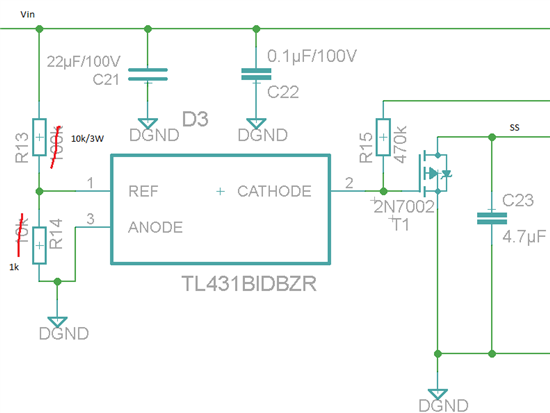
I've been having trouble using the TL431 as a logic switch for enabling voltage regulation through a lm5010 over a certain input voltage threshold. In this particular circuit, the idea is to prevent the lm5010 in drawing any current unless the input voltage is above about 25 volts. Vin ranges from 30 V to 70 V. My intention is: When Vin exceeds 25 V, the voltage across R14 will pass 2.5 V causing the transistor at the end of the opamp inside the TL431 to lead, pulling the cathode low, disabling the 2n7002 (R15 is a pullup) and lets C23 charge to the appropriate voltage required for the lm5010 to become active.
1. First of all, are there any flaws to the circuit?
2. I noticed the voltage across R14 follows the input at a rate of about 10 % as expected up until around 15 volts. Then the voltage increase decays. It does not reach 2.5 volts until around a Vin = 30 V. I figured it could be due to low Iref current, and decreased the resistance in the voltage divider. It helped a little, causing a little less decay above 15 volts. However, when the reference terminal of te TK431 reaches 2.5 V, the output cathode does not go low, but stays at 1.6 volts. And this is the strange part: The cathode follow the input voltage at a rate of 1/2 until about Vin = 14 V, Vka = 7 V. Then, the cathode voltage starts to fall again, until reaching 1.6 volts. I must be misunderstanding something here. Can anyone se what?


