This thread has been locked.

If you have a related question, please click the "Ask a related question" button in the top right corner. The newly created question will be automatically linked to this question.

Noise-Reduction Network for LDO and other question regarding PSRR improvement

Other Parts Discussed in Thread: TPS7A39, TPS7A49, LME49600, OPA1622, LM317, TINA-TI, LM337, OPA1612

Hello dear Ti community.

I'm using your LDO's for more than few years.

My first choices are TPS7A4701/3301 and TPS7A49/30 and TPS7A39 (dual reg in one package).

I found some articles about improving LDO performance in many regions, including noise, PSRR etc.

Those articles are listed below :

My questions are :

- may I use it those reduction network for regulators listed above? (positive and negative), I read this article and I think it should be possible for all IC mentioned above.
- if I can adapt those network then how to calculate that RC value to obtain to achieve good compromise? Which parameters of LDO should I take to calculate everything myself?
- how about drawbacks (excluding start up time mentioned in arcticle and ofc cost and solution size), is there anything else that I should care about?

My design is very similiar to reference and it's follow design note.

According to second article I've got questions about improving PSRR at LDO input.

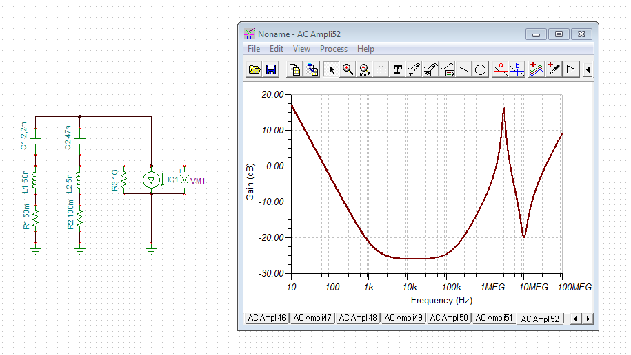
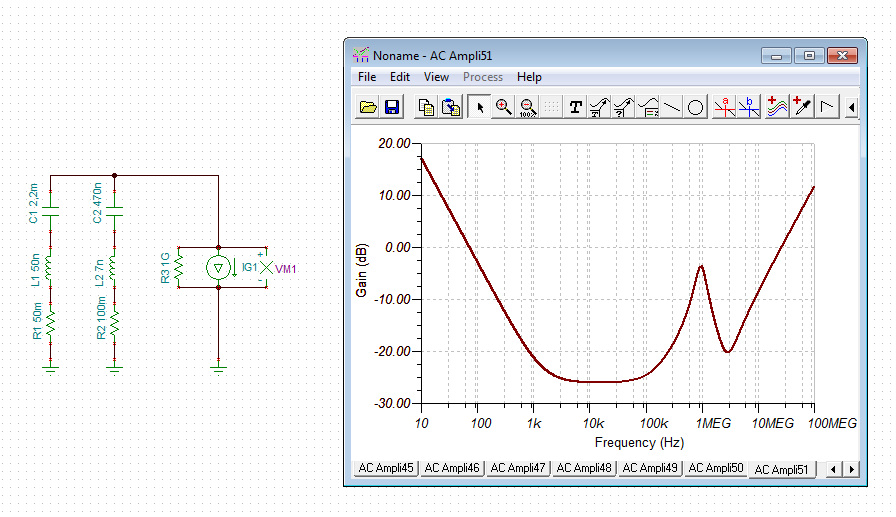
My PSU look like this :

IEC Inlet filter -> Toroidal transformer (hi quality) -> CRC snubber to damp trafo resonance -> bridge rectifier followed then by CRC filter (two big reservoir capacitors connected via small value resistor) -> LDO -> load.
Is there any chance to improve this design in terms of PSRR or overall performance?

I'm using those LDO's for audio application which include powering up DAC IC (or digital IC like SPDIF IC, DE/MUX etc.) or opamps (including hi current types like OPA1622 or LME49600).
So i want to achieve best possible performance with those applications.

According to Maxim desing note it would be best to place another LDO as a preregulator - but that solution will take some space and generate visible cost.
Maybe there will be some other ways to consider?

Thank you for helping me and your time.

  • Hi Mateusz,

    the OPAmp you plan to use have a so high PSRR that I don't think that much power supply filtering is needed, if at all. A pi-filter killing the highest frequencies in front of LDO can be helpful sometimes. Take a 10µH choke and two 100µF caps to form a pi. Add a 1R resistor in series to the choke to dampen any resonance and 470n caps (foil, X7R) in parallel to the 100µ caps. Take a choke with enough current rating and with as high as possible resonance frequency. Very efficient are 5 holes ferrites as choke. They provide a very high low frequency inductance (arround 10µH) and are very high ohmic even in 100MHz...1GHz range.

    Kai
  • So I should place your filter at my LDO input?
    How about those thing that I suggested above?

    BTW I was reading about tracking pre-regulator, does it make any diffrence? What is a main advantage of this circuit?
    I saw some, but almost all of them was build around two LM317 reg.
    Is possible to build it from two TPS7A4701/3301 (if it will improve something).

    How about those circuits?
    I assume for higher current I will need to use diffrent transistor (or darlington).

    www.edn.com/.../Simple-circuits-reduce-regulator-noise-floor
  • Hi Mateusz,

    yes, at the LDO input.

    Some numbers:

    Assume you are using the LM317 for producing the +15V supply. It generates 0.003% of 15V noise, makes 450µVeff in the band 10Hz...10kHz. Using a decoupling cap at the adjust pin reduces this noise by about a factor of ten, makes 45µVeff. Now take your OPA1622 with 100dB PSRR. The PSRR will reduce this noise to 450pVeff referred to input. The OPA1622 introduces a noise voltage of 2.8nV/SQRT(Hz), makes about 280nVeff in the band 10Hz...10kHz. This is a factor of 620 higher than the noise introduced by the LM317 through the supply voltage pins. So, do you really think, that there's any need to reduce the noise of power supply?

    Or take the ripple rejection of LM317. Assume there is a 120Hz ripple of 1Veff at the input of LM317 coming from the big storage cap behind the bridge rectifier. Ripple rejection of LM317 is about 60dB, makes 1mVeff at output of LM317. PSRR of OPA6122 is 130dB at 120Hz, makes 320pVeff referred to input of OPA6122. So, the 120Hz ripple is a factor of 880 smaller than the noise floor of OPA6122. Do you really think, that there's any need to improve the ripple rejection of voltage regulator? :-)

    Kai
  • Hello Kai.

    I heard that before, that I'm looking for an overkill power section.
    Especially when we take a look at OPAMP PSRR and LDO PSRR.

    But PSRR will vary with frequency anyway.
    I also think according to first article from my post, that I can easily afford two addition passive elements to improve my LDO in some areas - it will cost me virtually nothing :)
    I can even afford series cascade of two regulators (same type).

    In your opinion what should I take care about? If my power supply is good then what?
    PCB design?
    I always was a big fan of good power supply for audio devices because it's important.

    Could you tell me tracking pre-regulator circut? What is the main advantage of those?
    I saw that they were very popular years ago, when ultra loise LDO was expensive.

    I also use Schaffner Inlet filter (low current version), type FN-2090 which is superb stuff :)
  • Hi Mateusz,

    the little calculation I have done above is valid for the whole audio frequency range. So, there's nothing to improve. But, you are right, at higher frequencies the PSRR of OPAmp and the ripple rejection of linear voltage regulator fall down with a slope of about -20dB/decade. That's why I recommended the pi-filter in front of the LDO. As a 2-pole filter it improves the damping by 40dB/decade and is fully compensating the decrease of damping of OPAmp and regulator at higher frequencies. The same effect would have the two cascaded RC-filters in front of LDO shown in your link. The advantage of "my" pi-filter is, that the voltage drop due to load currents is smaller.

    Cascading of regulators is no good idea when it comes to high frequency suppression, because due the huge parasitic capacitance in parallel to the fat regulation transistor all the high frequency noise is shunted from the input directly to the output of regulator. Only for much lower frequencies cascading of regulators is of benefit. But in this frequency range there's no problem.

    In my designs I usually add a RC-filter at the supply pins of OPAmp. In stages with very high gain there's even a RLC filter. I find them very useful, because they do not also suppress high frequency supply noise, but they also stabilize the OPAmp circuit by isolationg the supply voltage from the load current changes of other OPAmp circuits. The resistors also minimize the ground return currents of the supply filtering and by this keep the ground plane free of supply noise.

    I have never used tracking pre-regulators.

    The signal ground is perhaps the most demanding issue when it comes to audio applications. Keep in mind, that you have up to 100dB or more of power supply rejection and 60dB or more ripple rejection. But you don't have any ground noise and ground voltage rejection! So, your supply line filtering might be lousy without any bad effect. But an improper ground management will totally ruin your apllication. It's the signal ground where you have to keep an eye on. Not so much the supply voltage... :-)

    Kai
  • Thank you for your reply :)

    Could you take a look into this?

    www.analog.com/.../AN-1120.pdf

    There is some things described that are my points of interest :)
    According to this PDF cascade of LDO will bring me some improvement in term of PSRR but in lower frequency (up to 1MHz or even lower), but it's still an improvement :)

    They also talk about pre/post filter, could take a look into that? They propose less complicated filtering.
    BTW if I'm going to use prefilter (your option or AD option) should I still use my CRC filter? Im using 4700uF - 2.5R - 4700uF config.

    RC/RLC filter at opamp power supply pins? What configuration?
    I'm using 10uF tantalum cap (solid or polymer) + 0.1uF ceramic + 1000pF ceramic at each power supply opamp pin.
    What value are you propose? 10R, or even more? I've got 10 opamps in my design so I can afford some resistors or breads to make my power supply better, I think bread will be better (less significant voltage drop, so I will maximize my dynamic range).
    So I will need 20 pcs for all opamps to be sure that everything is fine :)

    I was thinking about making signal ground and power ground (just like for DC DC converter) with signle point to connect them together (I assume reservoir capacitors will be best place to connect both ground together, or maybe should I connect them somewhere else?).

    If I use signal ground for OPAMPS and audio input (all feedback resistors connected to ground, LPF, etc.).
    Same signal ground should be used for LDO feedback and noise reduction capacitor? TI recommend that for their low noise LDO's (like TPS7A4701), same layout recommendation is ofter proposed for DC DC converters.

    I will build 4 layer board so I can spare one internal layer for signal ground and another one for power ground.
    But I've got question regarding power opamps load, I'm going to drive some significant load (headphones) so phono socket (jack) ground should return to power ground or signal ground then? Or maybe phono socket should be used as a point to tie them both together?
  • Hi Mateusz,

    Make a careful review of your board routing when using a split ground (signal ground, power ground) when you use a single point to tie the grounds together. You want to avoid having any traces with dynamic signals routed across the ground split. The return of signals crossing the ground split have to take a longer path to return through the single point connection, increasing inductance. I have seen plenty of switching regulator designs with dynamic signals (current feedback, voltage feedback, sync clock) that violated crossing the ground split and had more test/integration issues and lower performance than some designs with just a single ground on the board.
  • Hi Eric.
    I'm not using any kind of DC Converters (boost/buck/inverter) so I think that spliting ground could be a nice idea.
    Especially when I will build a 4 layer boad, when one internal layer will be power and one of them will be a ground (lets assume signal, directly below signal traces), whole area will be filled by copper (internal layer).
    3rd layer will be for power.
    Bottom layer could be my power GND and again whole board area will be filled with copper, probably there will be no need to trace anything at bottom layer or inner layers, so I can spare them for those purpose.
    My design is not that complicated anyway, most or even all traces could be easily routed without any vias (excluding vias for GND and power from inner layer).

    There will be only small splits introduced by solder pads of THT elements, vias and due to stray capacitance on sensitive opamp pins (I will remove copper from that area), so I will try to make ground layers continous as much as possible.
    This is why I picked 4 layer PCB - if my thinking is proper in this case, then it should be much easier to work with ground and return currents.

    How about that stackup?
    Tie point will be between reservoir capacitors.

    BTW Eric would you please take a look in to my first post and answer my question about those articles and pre-regulator circuit?
    It's hard to find any good answer about that, and those advices from AD document are not widely used, so I want to know should I use with TI LDO's and is it worth my effort.
  • Hi Mateusz,

    the low pass filter in the link are simple pi-filters with snubbers added to provide enough losses to dampen the resonance of L and C of pi-filter. These snubbers have the same effect like resistances in series to the L. But the voltage drop due to the load currents is smaller. I think that a pi-filter in front of LDO is a very good idea. But a pi-filter behind the LDO is not really needed in the very most cases, unless you have a HF-application with GHz-OPAmp or so. When it comes to audio applications simple RC-filters are enough. 10...100R in combination with 10...100µ can be chosen, depending on actual application. Aluminium electrolytics are sufficient, especially if you parallel them with 100...470n X7R. In stages with very high gain like microphone amplifiers, RIAA-pre-amps, etc. an additional 10µ choke can be helpful. Also these simple capacitance multiplier circuits like shown here:

    www.electronics-notes.com/.../capacitance-multiplier-circuit.php

    can be very helpful. These are state of the art decoupling circuits and can be used in the supply lines of stages providing very high gain.

    When it comes to splitting of signal ground and power ground I fully agree with Eric. Even if linear regulators are used a splitting of power ground and signal ground is no good idea. If the decoupling caps of an OPAmp circuit are not directly connected to the signal grounds of feedback resistors then the decoupling caps become ineffective. Using a power ground which is only remotely connected to the signal ground is the same as if you would use decoupling caps with 20cm long lead wires. And if you use several different planes in a 4-layer board for power ground, signal ground, a.s.o. you will add so much stray capacitance and parastic inductance that the impedance of wiring will become complex and will show heavy impedance maxima and minima. This is the best method to turn your audio application into a multi mode oscillator. :-)

    The best way to make OPAmp circuits work properly is to use a solid ground plane. This ground plane must be connected to the point where the GND pins of linear regulators are connected to each other. Have each OPAmp being connected to this ground plane, or, by other words, the ground leads of decoupling caps and the ground leads of feedback resistors should be connected to this ground plane, close to the OPamp. To deal with common mode noise, i.e. differencies in the ground potential at different locations of the printed circuit board, use balanced signals. Huge audio mixing consoles (Makie mixers, etc.) are using this concept. They do not have the power grounds and signal grounds splitted.

    Kai

  • Hi Kai.

    I've got some another question, regarding pi filter.

    Could you please describe performance of your pi filter in comparision with AD solution? Which will be propably smaller due to lower value L :)

    Another question is, if I will use RC filter for OPA, then I will introduce voltage drop (and affect dynamic range a little), but it will make my power supply high impedance.

    Maybe I should use L instead of R? Or maybe both (R in series with L), how about that?

    Should I use common R/L for all opamps? (then I will need on per power line) or should I use dedicated one? Two filers per one opamp.

    I'll include pre-filter in my application, but there is one question, when it should start to work? Most regulator PSSR is getting lower in range of 10KHz - 100KHz.

    At this moment I'm using as described in my earlier post CRC filter from my reseirvoir caps, how about replacing my low values resistors with chokes/inductors (less voltage drop and maybe better performance), could you suggest me something in that matter?

    CRC is the simplest solution and work fine, but maybe there something more to play with? I'm using 2x 4700uF per line.

    After reading an AD article about noise reduction network I'm going to try it in my LDO design.

    But I'm still unsure about tracking pre-regulator, opinions are often positive, but almost all designs are builded on LM317 which is almost 50 years old part, it would be nice to gain some PSRR at lower freq if possible :)

    I've got another, maybe uncommon question, but I saw those circuit in LT3042 note.

    One of proposed design is using external, hi performance voltage reference, my concer here is:

    - does it improve LDO performance in 1/f range (10Hz and below) ?

    - or LDO is used just to improve current capabilities of LTC6655 ?

    Or maybe it's win-win situation and using that kind of circuit will improve both?

  • Hi Mateusz,

    The ADI post on noise-reduction network using a feed-forward capacitor and resistor is also mentioned in some TI datasheets and app notes. See this app note: www.ti.com/.../sbva042.pdf

    Here are more TI app notes on PSRR and LDO Noise:
    www.ti.com/.../slyt202.pdf
    www.ti.com/.../slyt489.pdf

    The ideas in the Maxim app note to use input filtering or an additional LDO in series will work to reduce the amount of noise that passes from the input to the output of your LDO. However, to get the specified PSRR performance in an LDO, you usually need 1 V of headroom: Vin - Vout = 1 V.

    Pi filters are used to filter in both directions. They are common in RF designs, where power supply noise is filtered going to RF components and high frequency RF signals are filtered from passing back through the LDO. Pi filters can also effectively be a 2 stage LC filter if there is enough inductance between the input source the first capacitor of the pi filter. As Kai mentioned, make sure all of your high-Q circuits are correctly damped. Here is a paper on filtering power supply input filters: www.ti.com/.../snva538.pdf

    I also suggest you do some calculations to determine your actual noise spec for your design. Then you can approach it as an engineering design rather than a science experiment. It is hard to make design trade-offs when your requirement is the best possible low noise performance without quantification.
  • Hi Mateusz,

    the L is equal in both variants, but the R in series to L differs. You can run a TINA-Ti simulation by yourself to see the difference of both concepts.

    The R in the RC filter of OPAmp increases the supply impedance only below the corner frequency. When using 100R + 100µF the corner frequency is 16Hz. Of course, if you have very high load currents or supply currents the voltage drop across this filter R must be taken into consideration.

    Each OPAmp should have it's own RC filter in the supply line, because the idea of having the supply filter is to decouple the OPAmps from each other. Usually you can use one RC filter for a double OPAmp.

    The corner frequency of pi-pilter in front of LDO is not of so much importance. The idea is to improve the ripple rejection at high frequencies. So, take a 4µ7...10µ choke with a resonance frequency of at least the unity gain frequency of OPAamp, which is about 10MHz for the OPA1622. The filter capacitance of pi-filter (here the second cap) should be about 1/10 of the storage cap of bridge rectifier. So, for a 2200µ storage cap 220µ is adequate for the pi-filter. 10µH + 220µF gives a corner frequency of 3.4kHz. To prevent ringing a series resistance of R >= SQRT(2L/C) = 0R3 is needed. This is in the range of ESR of 220µ electrolytic, if you take a standard aluminium electrolytic. So, no additional series resistance would be needed. If you place a 220n...470n X7R in parallel to the 220µ electrolytic and take a 5-hole-ferrite-choke for the 10µ choke you will get a pi-filter which shows a beautiful damping from 5kHz on up to the 100MHz range.

    The CRC filter you describe is helpful when supplying a power amplifier where a regulator cannot be used. But in an application with regulator a CRC filter in front of LDO does not make much sense. To fabricate the pi-filter just put the 10µ choke and the 220µ cap behind the storage cap of bridge rectifier.

    I see absolutely no need to use this LT3042/LTC6655-5 thingy or tracking pre-regulators or any other exotic stuff. Remember my little calculation above. You have so much headroom when using a high performance OPAmp, that there's no need for this. Just take a LM317/LM337 pair with the above pi-filters at their inputs, have a suited RC-filter in the supply line of each OPAmp and you can forget these supply noise and ripple rejection issues.

    Kai
  • Hi Eric and Kai.

    So I need to choose? Noise reduction network or feef-forward capacitor in my design?
    There is no option to place both in this case?

    I was asking about Maxim note and tracking pre-regulator due to improve PSRR with rather simple method (excluding costs), but series cascade of LDOs give rather poor effects.
    I was reading about tracking pre-regulatos and I found that useful, but I still got some concerns.

    "it does *not* fed the second reg with a voltage regulated relative to input ground. Instead it maintains a contant voltage across the second regulator. Which is a subtle but important improvement: the second reg has a constant voltage across it, so the error amp inside it is ONLY dealing with load regulation. The line regulation issue - dealing with incoming noise - is solely the job of the first regulator"

    I was curious does it even matter today, because most of this circuits was presented years or decades ago when LM317 and LM78xx was only affordable regs.

    According to Kai post.

    So RC filter for powering opamps it's a good idea, but I just need to calculate corner frequency, I assume lower will be always better :) ?
    I will probably use 10R + 10uF = ~ 1.6KHz.

    Would you be so kindly and show me those chokes are you mentioned few times? Performance of those pi filter looks very good.

    I was asking about LT3042 with external voltage reference because it improved 1/f noise and maybe some other parameters, but that was not descirbed anyway, LTC6655 is hi performance voltage reference.
    Question is does it 1/f matter in audio application? I saw some ADC designs with REF feeded with low 1/f voltage reference source.
  • Hi Mateusz,

    I would take a choke of the 06H-series from Fastron:

    www.fastrongroup.com/part!show

    1/f noise is usually no issue in audio apllications. The PSRR of OPA1622 is 140dB at frequencies below 100Hz. If this is not enough for your apllication then nothing will be enough. :-)

    Kai
  • Thank you Kai :)

    Anything in SMD case instead of 06-H inductors? Or alternative solution anyway?
    I'm looking for something that will be easily available in mouser or farnell :)

    So, should I consider something besides my questions? Any advices?

    BTW it might be stupid question, but how to calculate "right" value of output capacitor?

    Let's assume that I will place recommended value of COUT at LDO output, but almost always it is followed by another big electrolitic capacitor, which value might vary - my concern here is why is it placed or how "they" picked that value?
    For me it look like blind man job in many cases.
  • Hi Kai.

    I've got one question, should I really care about SRF ?

    If my OPA will be unity gain at X MHz then should I pick something that will match it (or even higher freq).
    I saw that may chokes with 10uF got similiar SFR (10-20MHz) but there are some with even higher SRF like 100MHz.

    I assume that SRF will be important if I want to build hi perfoormance pi filter which will be dealing with very high frequency.

  • Hi Mateusz,

    5 hole chokes are also available in SMD. Würth has them:

    katalog.we-online.de/.../WE-SUKW

    There are many other distributers which have these ferrite chokes. Search for "6 hole choke", or "UKW-choke" or similar.

    The SRF is of importance of you have a mixed analog digital application. Also, 5 hole choke provide a very high saturation current, because the "winding to ferrite volume" ratio is very low, which keeps the magnetic flux in the ferrite also very low. The saturation occurs at much higher currrents compared to standard multi-winding chokes.

    The value of output capacitor of LDO should be in the range what the manufacturer recommends. There's no need to increase the output filter capacitance of LDO to extreme values. Many "high-end" audio developers do that. But this has not to do with good engineering. Designing an amplifier is more a ritual act for them. They only use components which are hand-made in full moon nights by a group of virgins. These engineers are not following rules, their intention is to break them. They praise their products as unparalleled originals. You cannot discuss with them, because they don't want to discuss. They do only preach...

    Kai

  • Hi Kai :)

    How about using rather "classic" choke like this one :

    For pi filter? Or i should stay with your recommendation? BTW would you be so kindly and give me some more info about perofmance of those filter?
    I will place 1000uF capacitor after choke/ferrite (low ESR type), and if needed I will place damping resistor in series.

    I was asking you about LDO output capacitor because range of LDO stability vary between 1uF to 100uF (sometimes manufacturer recommend mixing out capacitors eg. ceramic + tantalum).
    But that range is often metnioned as a stability choice not performance (or even cost ratio), I was thinking about placing something bigger, like 100-1000uF.
    I saw so may designs with even bigger caps at output (1000+ uF or even 10K).
    So if my LDO is stable within range of 10-100uF then there is nothing to benefit from?
    I'm using local reservoir capacitor for all opamps (not mutual big cap for all of them, rather dedicated 10uF for each one).
    As you said, most audio devices are engineered poorly or even without proper knowledge.
    So there is many questions and things that needs to be clarified or learned again.

    In your previous post you told me that I shouldn't care about cut-out freq of pi filter when using in front of LDO.
    Question here is what matter at all? Cost, solution size?
    I know that SRF will vary, lower uH chokes will achieve higher SRF, I also should care about current (lower current chokes sometimes are better in terms of SRF).

    I don't care much about money, because most costs of pi filter will be oriented at choke anyway :)


  • Hi Mateusz,

    there are two ways: You can believe the self-declared experts which put 10,000µF caps at the output of an LDO. And if you really believe them, then you must take 100,000µF, because it must be even better than 10,000µF, quite obviously. Or you believe your own brain and the numbers.

    Calculate the worst scenario as I did with the simple calculations at the begin of thread. Then you know how much ripple rejection you need and how much filtering.

    It's not sexy to put a 100,000µF cap at the output of LDO. It's what an desperate idiot would do. But it's sexy to achieve a maximum of output with a minimum of input. And believe me, 100,000µF aren't really needed at the output of a LDO in an audio application...

    I have seen very expensive audio mixing consoles which do have only 100n decoupling caps at the OPAmps. No pi-filters and other stuff at all. But the microphone amplifiers with their high gain were designed much more carefully. That's the right way, to do what's actually needed.

    Kai
  • According to datasheets of opamp and LDO that I'm using it would be best to build a PI filter that will be able to work from 10-100KHz above.
    To remove any ripple that will be passed trough due to LDO and OPAMP PSRR performance (which is low at higher freq).

    I will stay with your knowledge and I will build a pi filter that you proposed.
    I assume your proposed ferrite will perform better than typical 4.7-10uH choke with SRF of 10-50MHz ?

    BTW should I care about shileded/unshileded choke/EMI filter in my application?
    Because there is plenty of chokes and filter to pick.

  • Hi Mateusz,

    I think your power supply storage cap behind the bridge rectifier should be 2200...4700µF. The pi-filter in front of LDO should have 220µF. With your shielded 4µ7 choke this will give a corner frequency of about 5kHz. This is ok. If you take a standard 220µF aluminium electrolytic with normal ESR you will not need to add a series resistance to dampen the resonance.

    Additionally to this pi-filter you should add the ceramic cap to the input of LDO the datasheet is demanding. The ESR of 220µF will also help to suppress the parallel resonance of these two caps.

    Kai
  • Hi Kai.
    May I ask you, why should I remove one of my reservoir capacitor?
    Few questions, should I bypass reservoir capacitor with ceramic/film? You said that I should bypass capacitor after choke with small ceramic/film is that advice is still alive?

    OFC I will use 10uF capacitor at input pin of my LDO (+ 0.1uF ceramic if needed to provide better decoupling).
    If I'll use 220uF capacitor then resistance needed to damp choke will be aprox. 0.2R, am I right about it?

    Question about SRF, if I pick choke with high enough SRF then that choke will perform better in my application? Am I correct?
    You said in previous post that I should use choke with SRF at least in region of opamp unity gain bandwitch.
    So I picked choke with 50MHz SRF because I'm using opamps like OPA1612 which are rather wide bandwith (~ 40MHz).
    This is rather diffcult task to find a choke with high SRF which will be capable to pass high current and it will be rather high value (more than 1uH).

    If SRF is important here then I can pick lower uH choke, like 2.2uH or even 1uH and use a bigger capacitor (470uF for eg.)
    Something within 1-10KHz corner freq will suit me well.

    I've got another question regarding reservoir capacitor, ATM I'm using very low ESR caps like Panasonic FR, or Rubycon ZLH, should I stay with those? Or maybe I should try diffrent aproach and pick something else?
    I know ESR matter in that place, I'm using single schottky diodes as a bridge rectifier (4 diodes, full bridge).

    I just wanted to be sure that I'm not going blind with those.
    I just don't want to follow those stupid "audio rules" that you described above, which is a real plague when you need to know or learn something, because so many people are making same mistakes over and over again.
    Some my questions may look stupid, but there is so many wrong answers around internet that I'm looking for clarification rather than sharing some crazy ideas with others, like most audio magican does.
  • Hi Mateusz,

    I appreciate your last paragraph about not blindly following "audio rules". Physics and math can be used to explain behavior of electronics and if you dig deep enough you will find good explanations. I've found text books and manufacturer app notes to be the most reliable in general. There are a few reputable design service firms and experts to rely on as well. We strive to provide factual, informed content on e2e.ti.com. Unfortunately there is a lot of incorrect information online.

    As frequency increases past SRF for an inductor, the impedance of the inductor starts to decrease like a capacitor. Likewise, a capacitor impedance above SRF starts to increase like an inductor. The impact on a low pass filter is the amount of filtering starts to decrease above SRF.

    You can always trade off the inductor and capacitor values to get the filter corner frequency you need. Reduce the L and increase the C to keep the same corner frequency.
  • So higher SRF will make my LC filter better in term of rejecting incoming noise.
    BTW Eric, I found so many audio advices bad or poorly written that I'll not going blind again.
    Even simple things could be badly engineered or misunderstood when we're talking about audio.
    Many people missing a point here, thinking that audio is beyond everything else, making some things with overkill fashion, which is not good.

    So my thread might be stupid, because I'm asking over and over again about things that nobody cares in audio, when performance is often not adequate to price.
    I'm really glad that i found E2E forum so helpful in so many terms.

    So is there anything to care about power supply and pi filter itself?
    I picked a choke with low DCR, high SRF, and enough current capability.

    Am I missing something here?

    Eric may I ask you for a little favor? Would be so kindy to simulate something for me on your Tina-Ti software?
    I just wanted to check how pre-regulator builded from two TPS7A4701 will work in real life, but your software is really hard to learn for me ATM.
    I was wondering about that solution for few days, it might be not best idea, but I'm just curious about performance of those.
    I just want to know does it bring ANY benefits in comparision to standalone regulator.
    There is little to none knowledge on internet about that, many webpages are few years old and look outdated.

    I'm not asking about this on audio forum, because I will not receive any objective information about it, just subjective things (or even funny) about who heard this and that, or he remembered this circuit to be superior to XYZ, but curcuit ABC is still somehow better.

    I've got another question about bypass capacitor.
    If I got one big capacitor it's often recommended by almost everyone to bypass it with something (foil or ceramic), the question is, how to calculate right value of that capacitor to achieve good performance?
    From my observation most people are using 100nF capacitors almost everywhere, because they are cheap and available.
    But for me it's look like "audiophilia nervosa" similiar to replacing capacitors all over the place to gain "better audio".
  • Hi Mateusz,

    many decades ago I was in the same position like you. But at my time there was no internet, no forums, no good library. You could only learn from databooks, if you could get some, and from electronic magazins. The most we learned from experimenting and measuring, by trial and error...

    The pi-filter in front of LDO is formed by the big storage cap behind the bridge rectifier, which I assume to 2200µF and the 220µF at input of LDO. Between them sits your 4µ7 choke. The 220µF shall be paralleled by a ceramic cap of 220n...470n. As the 220µF shall sit directly at input of LDO you can use the ceramic cap which is intended to be also there for the LDO:

    C4 is the ceramic cap TI recommends at the input of LDO, here 10µF, e.g.. It's part of the pi-filter at the same time. An additional 220n...470n cap, as recommended above, is no longer needed. The 10µ takes the place of 220n...470n cap.

    Yes, 0R2 would be needed to dampen the resonance formed by the 4µ7 choke and the 220µF cap. But this 0R2 usually sits already as ESR in the 220µF cap.

    The 4µ7 choke you have chosen is alright.

    I see no need for ultra low ESR electrolytics as storage caps behind the bridge rectifier. A too low ESR can result in huge inrush currents when powering on the supply.

    One last word to decoupling caps. If you want to put a small capacitance in parallel to a big capacitance, another sort of resonance can be introduced: The inductance of the one resonates with the capacitance of the other.  A heavy impedance maximum can occur, which erodes the decoupling performance at the resonance frequency. In the following simulation you see a 2200µF axial aluminium electrolytic paralleled by a small 47nF. Then, in the next simulation the same electrolytic is paralleled by a 470n:

    (20dB means an impedance of 10R, 0dB is 1R and -20dB is 0.1R.)

    It can clearly be seen, that the impedance at the peak with the 47n cap is ten times higher then with the 470n cap. So, when big electrolytics with lots of inductance have to be paralleled by a smaller cap, then 47n..100n can be too little. 220n...470n can be more useful. Also, do always use radial electrolytics and no axial!

    Kai

  • Very useful information :)
    Thank you.

    But may I ask you why should I stay with one reservoir capacitor instead of bigger (4700uF vs twice that capacitance).
  • Hi Mateusz,

    there is a rule of thumb, that you take 2200µF for each Ampere load current.

    Kai
  • Alright.
    I never heard of it.

    Maybe because in audio world there is always place as many capacitors as you can or bigger is always better.

    I've got a question regarding LC filter but in relation with passing audio signal trough it (I don't want to start new thread, because it somehow related with my previous question).
    ATM I'm using RC LPF (input) for my audio amplifier, corner freq is located at ~ 400KHz to provide flat response at 20KHz.

    If I'm going to replace resistor with inductor should I take care about something?
    RC is straight forward, but I want to provide good attenuation (L should be better) but I don't want to introduce any distortion etc.


  • Hi Mateusz,

    there are several reasons why audio low pass filtering should be done by RC filtering instead of LC filtering, if possible. One is that resistors can be fabricated with much less production tolerances compared to chokes. This is important for the stereo balance. Components for audio filtering should be very precise to avoid any stereo imbalance. Another is that the low frequency impedance of a choke might be too small to isolate the filter capacitance from the driving OPAmp. The OPAmp can become instable. Also, remember that LC-filters tend to introduce excessive ringing which need a series damping resistance anyway. So, it's best to stay with RC filtering.

    There's another rule of thumb: An audio pre-amplifier is allowed to have a bandwidth of 20Hz...20kHz with a drop in the frequency response of up to 0.3dB at 20Hz and 0.3dB at 20kHz. For a single RC low pass filter 0.3dB at 20kHz means a drop of 0.2dB at 16kHz and a drop of 3dB at 73kHz. This sort of bandwidth limitation is absolutely unhearable. At the same time it helps to create an audio pre-amplifer which is stable and insensitive to HF-noise.

    Usually, you will have several low pass filters in an audio pre-amplifier. One at the input and others for useful bandwidth limitations in the individual feedback loops of OPAmps, in order to the introduce phase lead compensation. Then you must spread the 0.3dB drop over all the low pass filters. When having ten low pass filters, e.g., each should provide a drop of about 0.03dB at 20kHz. Often it's a good choice to have 0.1dB...0.2dB drop alone in the input filter. The remaining low pass filters can have 0.01dB...0.02dB each then.

    Kai
  • Hi Kai.

    So I assume, that my 1st order LPF at amplifier input should be set to ~ 80KHz to reject noise as much as possible without sacrificing linearity.
    This is very diffrent aproach, because most audio devices are made with higher linearity in range of 20Hz - 20KHz.
    This is why my LPF was set to ~ 416KHz to achieve perfect response at 20KHz.

    I was afraid that LC LPF will not be suitable in my application, I ofc don't want to overload my dac output section with capacitance.

    I've got a concern here, I've got an input stage which is using few opamps, then each one should be bandwitch limited (via NFB) and each one after another should be adjusted to cut a little lower than previous?

    Am I right? It could be difficult due to capacitors selection in pF range.

  • Hi Mateusz,

    an OPAmp must have a unity gain bandwidth of much more than 1MHz to be able to handle audio signals of 20kHz. It's just the gain reserve of OPAmp (loop gain) which decreases the distortion down to unhearable values. Without a linearizing feedback loop an OPAMp would produce distortion in the % range. On the other hand, the high bandwidth of modern OPAmps make them sensitive to HF-Noise. So, a bandwidth limiting by the help of low pass filtering stabilizes the OPAmp enormeously. That's the right way: Use an OAPmp with very high bandwidth, but limit the bandwidth to the wanted signal range by the help of low pass filtering.

    There are absurd audio frequence responses in the high-end audion scene (you know the amplifiers which are made by a group of virgins... :-) Typical studio mixers have a frequency response with a drop of 1dB at 50kHz and a drop of 3dB at 100kHz! And by doing this they fullfill international standards. The strict bandwidth limiting shall make the mixer more immune against HF-noise coming from radio stations and cellphones.

    I havn't understood what you mean with LC filtering at output of DAC.

    Only the first stage of amplifier, the input stage, should have a lower corner frequency of low pass filtering, because here the most HF-noise can enter your amplifier.

    Kai

  • Hi Kai.
    May I ask you for an email to talk about other thigns not related to this thread?
  • Hi Kai.

    Would you be so kindly and take a look into TIDU034 from TI site?

    I've got some question about this design and I really want to know your opinion about it.
    Maybe you'll be able to give me some advices about it.

    I've got some ideas but I want to hear your opinion first.

    BTW I did some steps to add that LC filter that we're talking about and I also found a good capacitor with ESR that will damp resonance :)

  • Hi Mateusz,

    what question do you have?

    Kai