This thread has been locked.

If you have a related question, please click the "Ask a related question" button in the top right corner. The newly created question will be automatically linked to this question.

LM22675 - burning on start

Other Parts Discussed in Thread: LM22675

Hi,

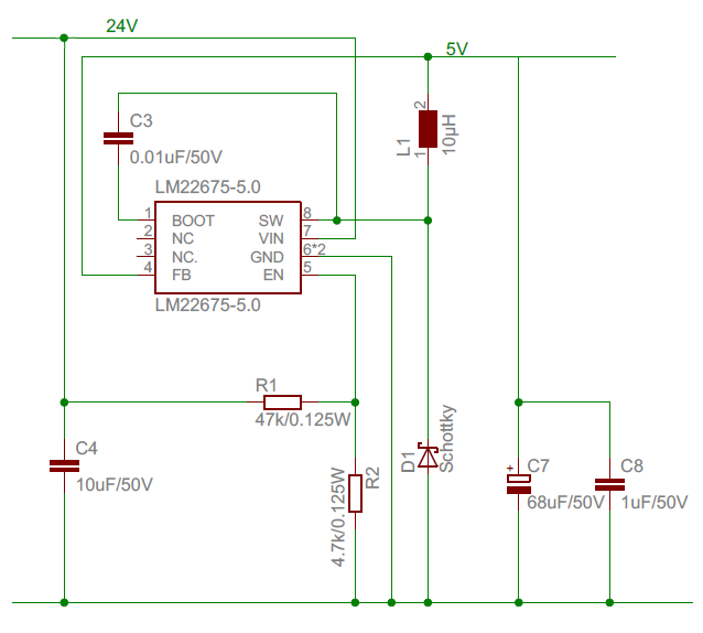
we are facing problems using lm22675 part. From time to time when we switch the system on the parts are burning. The circuit was developed using webench designer and the layout is very close to de recomended on datasheet. Most of the cases the part present a short between SW and GND pins after failure, one case a short between Vin and the same pins. The board is a two layer board, the circuit was developed with webench to have a 3.3Vdc from a 24V(20~30V) source. We are lost here, since we have verified almost everything. Can you help us?

  • Thank you for your interest in Texas Instruments power solutions.

    Sorry about the troubles you are having, i would definitely like to look into what is causing this. In order to help you we will need a little more detail about your design (design requirements and schematic to start,  layout and any captured waveforms  would also be helpful). If you want you can post here in the forums, but you are also welcome to email me directly if you do not want to post publicly.

    Regards,
    Tommy Jewell
    WEBENCH Apps, TI
    Tommy.Jewell@ti.com
  • Hi,
    I'm sorry to resurrect this old thread, but I am experiencing exactly the same problem. The LM runs for a short time, but then burns and I can measure a short between GND-VIN-SW.

    This is my schematic:

     In front of this, there is a bulk capacitor in form of 100uF//1uF.

    Some Details to the components:

    L1 : L = 10µH ; Irms=1,5A.

    D1: Urrm=40V ; If=1A ;  Vf=700mV.


    The application behind should not draw more than 600mA, so the current ratings should be ok.


    The parts are not exactly, but do come very close to the ones recommended, and yet  the LM constantly breaks down (It's broken down 3 times, and it works once). 

    Some help would be greatly appreciated, I'm really getting frustrated by this.

    Thanks ! 

  • Hi Lennart,

    Your are right, 600mA out shouldn't be a big problem for the IC so lets just start by verifying some things that may seem overly basic:
    I noticed you said "should not draw", are you able to verify this? (can you measure the IC input current or inductor current? If your load is digital is there anytime that it presents something close to a short?)
    Please make sure the exposed pad on the back of the IC is properly soldered down or the IC may be overheating.
    If possible can you check the SW node during operation and see if there is much ringing? 

    Your inductor value also seems a little small. At 500KHz at your duty cycle you get an inductor peak to peak of 800mA, or a peak value of about 1A. Though this should still be fine for the part, and larger inductor may increase reliable operation by reducing the current swing.

    Best regards,
    Tommy 

  • Hi Tommy,

    first off I'd like to thank you for the fast and competent answer, help is really appreciated.

    Now to the topic:

    The 5V-Output is merely used to supply 5 sensors, whose digital outputs go directly to a microcontroller. The sensors are all in order, so there shouldn't be anything similar to a short. I haven't measured the current on the output line yet, but it should be the sum of the sensor's operating currents (which sum up to a max. of 600mA, according to their respective datasheets). I guess while loading the bulk capacitor a higher current is drawn, but only for such a short time that I don't think any part gets destroyed by this.

    Regarding the heatsinking, we do have an issue which I noticed rightaway: There seemed to be a misunderstanding between us and the PCB-manufacturer, who covered the powerpad with solder resist. The Pad is therefore not directly soldered to the ground layer, which obviously difficults heatsinking. Although this is an issue, is it really a factor which makes the difference between total meltdown and normal functioning of the IC? I haven't had the opportunity to check the heat development, but I can't really believe that this is the only issue (although it would explain why one PCB works and the other two don't, since the one that works is the one that does not have solder resist and is therefore properly soldered).

    I'll try an measure the ringing once I get my hands on new ICs.

    Thank you very much for your help,

    Lennart


  • Hi again,

    I just scavaged an LM from an old PCB, removed the solder resist on my new one and properly soldered the powerpad onto the ground layer. The result ist that it, again, worked for a while. I then unplugged the power cable, and when I wanted to plug it back in it had a short between the three above mentioned pins (again !).
    I am not completely sure, but the the burning seems to occur when I unplug the PCB. How could this be explained ?

    Update: I'm pretty sure I've found the error. I was looking for a bigger Inductor, when I noticed that the Inductance of the one I've built in so far looks like this:


    I really feel shafted right now. I'll try to find a bigger Inductor to replace this one and report the forthcoming.

    Regards,
    Lennart

  • Hi Lennart,

    Proper connection of the EP is actually very important for this part, not just for heatsinking but also for optimal electrical functioning/protection. And with part failure its often times not just one thing but a summation of many parasitics that lead to the parts destruction.

    That being said, I not sure off the top of my head why turning off the source would cause the failure you see (though I'm intrigued) . Unless your source  is doing something nasty when you unplug it, or if your layout has long thin traces that are causing large parasitic inductances to do wierd things.
    I'm not sure if you have access to an oscilloscope but it seems like looking at the voltage waveforms may be helpful here. If its happening when you're unplugging it seems like it might be voltage stress on a pin. (Most likely Vin or SW).... Or if you have any other power sources you could see if they achieve the same behavior.

    Best regards,
    Tommy