This thread has been locked.

If you have a related question, please click the "Ask a related question" button in the top right corner. The newly created question will be automatically linked to this question.

LM3671: Excessive Current Consumption with very light load

Part Number: LM3671
Other Parts Discussed in Thread: BQ24040, ALLIGATOR, TPS62740

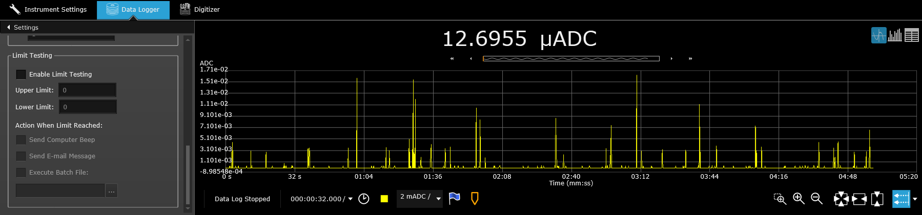
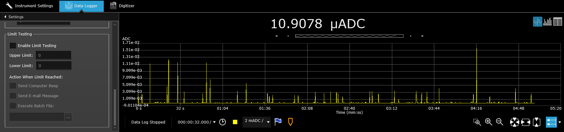
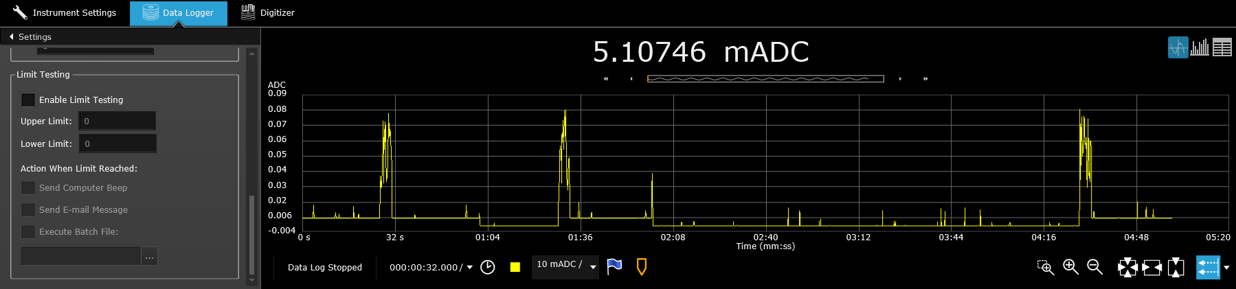
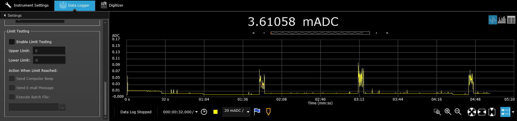
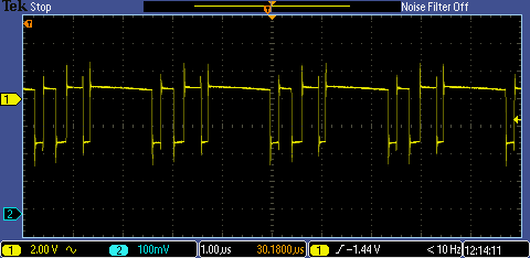
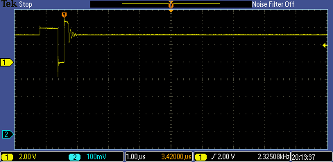
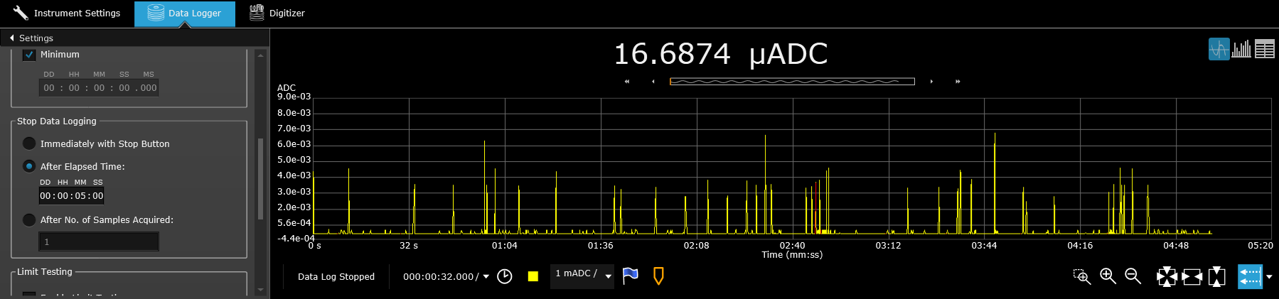
I have a product where we're using the LM3671-ADJ. I'm attaching my circuit but the part functions properly except sometimes when our board goes to sleep I am measuring it pull ~5-6mA when it should be ~100uA.

While trying to debug if this was a hardware or a firmware issue I touched the board in the area of the feedback circuit and the current consumption dropped to the ~100uA level. I'm not 100% this has something to do with the LM3671 so I thought I'd post to see if anyone had any ideas. The board is only about 1" square so trying so isolate what is being touched is difficult but it definitely seems to be just the filter parts.

Another other thing I've uncovered is that if the board is pulling ~5-6mA and I touch the filter circuit I think the current consumption briefly increases before (~13mA) before dropping to ~100uA.

The last bit of information is that if I activate the motor for 1 sec and the board will settle back to the ~5-6mA mode and I can repeat this cycle of touching to bring the current down and activating the motor (which draws ~50mA) to get it to this 5-6mA mode.

Hopefully someone has some great ideas and it doesn't mean a new board layout since we've already started production.

Thanks,

George

  • Here's some scope shots showing that the regulator is switching modes when going from 5mA to 100uA current consumption. That's to be expected but is something else the real issue or is there something with the filter on the regulator output that is building up a charge and drawing the 5mA until I touch it which drains the charge?

  • I ran some tests this morning and hopefully someone can help explain the results.

    1. I removed C11 (equivalent to C1 in the reference schematic in the datasheet). By doing this the current drops to a deep sleep value of ~30uA. I was not able to get the circuit to "stick" at 5mA like before.
    2. I changed C11 to 10pF and this acted the same as with C11 at 6.8pF
    3. I replaced C11 with the original value of 6.8pF and removed C12. With this circuit the value actually seems to pull more current, ~7mA, but when I touch the circuit I can only see an increase in current and it never drops below the 7mA consumption.

    What confuses me most about this is that if removing C11 is the answer to this problem it goes against the recommendations in the datasheet that at lower Vout you don't need C (C12 for my circuit). Vout is set to 3.1V which is well about the cut off voltage of 2.5V for not using C2 so I must be missing something.

  • Thanks for posting your schematic and waveforms. Is there anything else on the 3.1V output besides the motor?

    Go ahead and disconnect anything on the output (remove FB5 for example) and see if the high current is still there.

    Can you add Vin and Vout to the waveform and zoom in to about 5 or 10 usec when it draws the high current?
  • Hi Chris,

    Yes, there's a BLE module and an accelerometer. I can unplug the motor from the J3 connector and that doesn't impact the results. I'm watching the bench multimeter and I can see the system go from deep sleep at 30uA to sleep at 300uA periodically. That is the current level during normal idle times. If there's Bluetooth traffic that number jumps up to ~15mA. There's different level that the motor can operate at but with the tests I'm running now the motor pulls ~50mA for 1 sec and then the system goes into it's sleep mode.

    Unfortunately my scope only has 2 channels so I can't capture all 3 at the same time. The Vbat is connected to a Li Ion battery. Vin to the LM3671 has the 4.7uF on it's input and that's in parallel to the 1uF hanging off of the Vbat/OUT pin of the BQ24040 battery charger.

    Right now I have C11 removed and doing some power cycling tests to see if I can get it into this 5mA mode again. It appears that this is a "fix" but we've already got 6,000 boards built with C11 mounted so I need to be 100% confident in any changes I make so if we need to rework it's only done once.

    Thanks,
    George
  • For reference here's some additional scope plots. 

    Here's when the motor is running and pulling ~50mA:

    And here's some shots when the board is sleeping and drawing less than 500uA. All I did was take single trigger shots until I saw some plots that were a little different. The last 2 are taken with a 1us time scale

  • And here's a couple of shots again with the board pulling ~30uA. I can't get it into the 5mA mode so I'll probably have to add C11 back on the board.

    I also forgot to mention that I'm being lazy with these plots and using the alligator clip for the ground.

  • Here's what it looks like with C11 back in the circuit and the board in the 5mA mode. I confirmed that you can touch the filter circuit and that drops the current consumption back in the uA range.

  • Thanks for this data.

    There are a lot of pieces to your system, so we need to isolate the power supply to debug the power supply. Can you apply a DC voltage from a power supply on its input, after the charger? Are you able to measure the load current with a meter or current probe?

    What is the voltage of your battery for the above data?
  • I am measuring the current with a Keysight benchtop meter which is extremely accurate. The battery voltage is ~4V when these shots where taken. The input to this design is basically after the charger as the output of the charger is connected to the battery. I can replace the battery supply voltage with a benchtop power supply if you think that will help isolate this.

    The load current is being measured by the Keysight which is inline with the battery for these plots.

    I sent you a PM with the complete circuit.

    Thanks for looking into this.
  • Ah, yes. You have a simple charger, not with powerpath, etc. Yes, replace the battery with a DC power supply and see if the behavior is the same. It may also change as this voltage is varied, so vary it from 4.2V to ~3.3V and see if the circuit works normally with C11 installed.

    When the circuit is drawing the higher current, what does the meter measure as the load current? Is this current DC or is is changing, with peaks etc.? Which waveform above corresponds to this state?
  • I had done that test with using a DC power supply in place of the battery and I believe the behavior was the same but I'll go back and run some additional tests. When I say the same I mean that the board gets into a state where it is drawing 5mA instead of ~35uA.

    I've run the board without C11 now since Friday night and activated the vibration motor many times. Every time I activate the motor I can see it pull ~50mA and then it settles down to the ~35uA range as it should. The circuit doesn't appear o sensitive to finger touching like it is when C11 is in place. About the only thing I've noticed is that sometimes after I activate the motor the current draw drops from 50mA to ~12mA for 1-2 seconds before it drops to the 35uA level. When I connect to the device and read characteristics the spikes in current consumption are extremely brief, barely visible, on the multimeter, so this appears to maybe be another instability state but it is able to "self recover" unlike when C11 is in the circuit.

    The higher current mode is what I call the "5mA mode" as this is the level that the meter reads when the board should be sleeping. With C11 removed this level is ~35uA. When I was looking at this on the scope I was seeing some spikes but I assume that is when the BLE was changing from deep sleep to sleep mode and doing watchdog events. The system will never be completely asleep for long periods since it has to wake up and advertise and do other tasks.

    Right now it really seems like the system is "more stable" with C11 removed and I have not been able to get it into the "5mA mode" with C11 removed. It bothers me that the original circuit was one that is supposed to be used as per the datasheet and that the removal of C11 is kind of opposite was what I would expect because at lower output voltages to remove the other pole, not the one that C11/R8 creates.

  • Since I already had C11 removed I thought I'd take the opportunity to run some tests using the DC power supply in place of the battery. I started with 4.2V and stepped down to 3.2V. At each level I activated the motor several times and confirmed that the current level would drop to the 35uA.

    At 4.0V I witnessed it get stuck at a current draw of ~13mA so I probed the switching node:

    As soon as I removed the scope probe the current level dropped to 35uA. I can run this test at 4.0V and most of the time I see the 12mA level for ~1 second but sometimes it lasts for 8 seconds. However I believe that it always does drop to 35uA unlike when C11 is in the circuit it will stick indefinitely at 5mA

    At Vin=3.2V the current rises to just under 1mA and the signal looks like this:

    So everything I'm seeing is pointing to the compensation network and the regulator getting into different states which are causing the higher levels of current consumption coming from the regulator inefficiency in that mode. I don't really care about the circuit at 3.2V as that is beginning to push the limits of the battery and the regulator since the output voltage is set at 3.1xV.

    If you still feel that adding C11 back in and running these tests with the DC power supply I'll do them but I'm beginning to think they aren't necessary and that we need to find the proper network to use for this situation.

    I'm not sure of the scope probes capacitance as I broke my Tek probes and only have some 3rd party probes which might have higher than normal capacitance. I haven't had this "extreme" sensitivity to capacitance before with regulators but I've also not worried as much about uA level of circuit operations either.

    I do need to figure this out and determine what to do with the 6,000 boards built with C11. Right now it's looking like removing C11 will help and possibly totally eliminate the problem but I need to understand this and be sure that we only perform 1 rework (if any).

    Thanks again for your help in figuring this out!

  • Here's some plots of the current consumption using the bench multimeter which is set to take measurements every 0.3ms (0.02 PLC). These are all using a DC power source instead of the battery.

    Here's plots without C11 mounted.

    DC Power supply set at 3.6V

    DC Power Supply set at 3.8V

    DC Power Supply set at 3.6V

    And here are plots with C11 back in the circuit. When you see the level drop from 5mA or 3mA (lower current with lower supply voltage) that happens because I touch the compensation network. The circuit continues along just fine pulling the expected sleep mode currents of ~35uA. The large longer spikes are when I activate the motor. You can see that after the motor runs the "resting level" of the current consumption only drops the 5mA/3mA level. This is very repeatable.

    DC Power Supply set at 4.0V w/ C11 mounted

    DC Power Supply set at 3.7V w/ C11 mounted

  • On the first waveform you posted yesterday, there looks to be an AC signal on Vin. You might add more input capacitance to stabilize the input bus and see if this has any effect.

    As well, can you send the part numbers for the inductor and 4 caps via PM?

    It does seem like there is a noise sensitivity in your circuit. So, you can try some things to see what it takes to get a low current consuming circuit without needing to touch it. You could try:
    connecting the GND of C12/R9 with a wire to the vias above the GND pin (instead of to the GND pad and into the PCB on the second layer),

    reducing the FB resistors by ~10x while keeping C11/C12 in place (but 10x larger vlaues) per www.ti.com/.../slyt469.pdf
  • Without understanding why right now I know that removing C11 makes the circuit more stable and less (or no) sensitivity to touch.

    I'm not sure about the AC component you see if the plot from yesterday, perhaps that's because it was running the circuit from the DC power source? Since the power source is a battery isn't that already going to be similar to an additional capacitor on the input?

    I hesitate to start lifting components and adding wires only because that's not a fix for the 6k boards already built.

    Also, you say to try and reduce the FB resistors by 10x but that will increase the current consumption at light loads. I'm not sure by how much and it may be negligible but if the pole is dependent on RxC I'm confused what this will do to help? I admit, I guess I've been lucky so far with all of our other designs as we haven't had to worry about the pole placements and have been able to just follow the datasheet guidelines.
  • I don't think I've shown you what the SW node looks like when C11 is in the circuit and the board is in the 5mA mode:

  • We just ran the test of changing the resistors to 1/10 the current values (523k/100k to 51k/10k) and the caps to 10x (68p/330p) and the board acts the same in that it gets stuck at the 5mA level and drops when I touch the circuit.
  • Let me take this chance to align on the expectations of the support offered here in E2E. We are here to offer our experience, advice, etc. in helping you to design the best product you can for your customers. (Others in the community are invited to do the same.) Your product is ultimately your company's and must be designed and validated by you (your company). We do not provide engineering or consulting services here. The final design, along with necessary validation and testing in your application/system/environment, is your responsibility at the end of the day.


    Now, back to the technical topic at hand. All tests described here are designed to provide information about the behavior that you are seeing, which then allows you to make the best decision about how to move forward. They are not necessarily 'solutions' to go and implement.


    Ah, looks like that waveform of SW was AC coupled. But I think you did send the same waveform at 5:10 on Friday? These waveforms point to the IC switching 'too often' as the cause for the higher current consumption. This could be a result of something your load is doing (drawing peaks of current every few usec, for example). Do you have a current probe to measure the inductor current and see if either of the 2 criteria for PFM operation are met?

    The battery should normally have a lower impedance than your DC supply, which is wired in, but this depends on what specific battery you have and its impedance. It might still be worth checking if more Cin and/or Cout improves the behavior with the battery.

    Does this same behavior occur on all systems or just a few of them?

    It is a good debugging practice to test your circuit and operating conditions on the EVM to see if the behavior is repeated. If not, then replace the components (L, C, etc.) on the EVM with yours and see if the behavior still occurs.

    I could not find any information about the DC bias of the Cin and Cout caps. Have you already checked this? The other passives looked reasonable.

    Thanks for doing the smaller resistor test. Different results would have indicated that noise was getting into FB. It seems that this is not the case. Have you tried removing C12 instead of C11?

    I realize that it is too late to use a different IC, but the TPS62740 or TPS627431 offer a fixed 3.1V output voltage with much lower Iq. This would make the standby current consumption drop from your ~35 uA to much less.
  • Hi Chris,

    Yes, I understand. I do miss the good old days when there actually were local FAEs that came and helped to support their customers. We did run tests initially and several boards under different conditions but thinking back I believe that we had done this before all of the deep sleep modes were implemented so we may have missed this. This also doesn't appear to happen to every board nor all the time. I'm concentrating on one board right now that does seem to happen most of the time and if it doesn't it happens after I operate the motor.

    I've used the TPS62x series on other designs but I think I chose the LM3671 for this one for a lower cost solution. I've never run across something like this before with a voltage regulator so it really through me for a loop (I guess that's a pun) when I discovered this.

    I'll get the details on the DC Bias specs but I would think I have enough margin since the input 4.7uF is rated at 16V and the output is 10V.

    I can't remember if I tried removing C12 instead of C11 (I think I did and didn't help) so I'll definitely do that and report the results.

    The 35uA is a combination of the Bluetooth, battery charger, accelerometer, and the regulator. Looking at the specs of the regulator it might be responsible for 1/2 of that!

    As a backup backup plan I did look at the LP5907MFX-3.1/NOPB this weekend. It's a linear regulator with the same pinout and looked like it could work but of course that's a fairly major rework so I'm hoping to not go down that route. The LM3671 was chosen as a balnce between cost and performance and I think the TPS62x were just a little too much for this product.

    Thank again for your help and I'll have the C12 removed results hopefully later tonight.
  • OK, removing C12 and keeping C11 resulted in slightly higher current consumption (~6mA vs the 5mA). The circuit doesn't appear to be sensitive to touch but I also couldn't get it out of the 6mA mode. When C11 was removed I could touch the board and it would drop down to the 35uA consumption until the motor was activated.

    I replaced the 4.7uF input capacitor with the same 10uF that's on the output. The circuit also doesn't appear to be sensitive to touch and it rests at 35uA. What's odd is that it will shift and run at ~300uA for maybe 10 seconds before it "self corrects" and drops back to 35uA. I was looking at the SW node when it was doing this and the plot looks the same as when the circuit is only pulling 35uA. I'll have to run some additional tests tomorrow and see how things look because I haven't seen it stick at the 300uA level since I started writing this.

    For record keeping here's a scope shot of the SW node with Cin=10uF (as opposed to the original 4.7uF):

    Here's a multimeter plot with Cin=10uF:

  • Just a quick note. I let the board run overnight and upon return it was still at the 35uA level. I activated the motor and it dropped to the 5mA mode. I touched the circuit and the level dropped to 35uA. I did this 3 times with the same results. I can't explain why last night it appeared to work and this morning it doesn't.
  • That's interesting that the input cap affected the behavior. It would be worth trying new caps with known good DC bias, from Murata for example.
  • So after I tested the board early this morning I left it disconnected from power since the behavior was different than what I saw last night. Now it appears to be be good again and not get stuck in the 5mA mode. This can't be a heat issue as very little current is being drawn when the board is just sitting there. I just measured the battery level and it's at 3.98V so it's still almost full.

    I'll let the board run for another hour and test again to see what results I get. If this is an issue of too low capacitance on the input I'd really be surprised. In the datasheet it states "The minimum input capacitance to specify good performance is 2.2 µF at 3-V DC bias; 1.5 µF at 5-V DC bias including tolerances and over ambient temperature range". I'm using an 0603 4.7uF rated at 16V with an input voltage of ~4V so this caps DC Bias curve would almost have to be a steep cliff in order to drop the capacitance that much. On top of that I also have an additional 1uF at the input to the battery charger and the power source is a 110mAh Li Ion so the concern of supplying current to the PFET shouldn't be a concern since the motor pulls less than 1C.

    I'm just trying to learn (and of course fix) this issue. Have yo been able to talk with anyone about why removing C12 seems to also impact the circuit's behavior? From all of these tests it seems that the issue is related to how the regulator goes into and out of PWM/PFM mode and that's causing the regulator to be less efficient and draw more current.

  • Yes, I agree that the effective capacitance is likely high enough. But we don't know this for a fact. These smaller batteries have a higher internal impedance, which might be affecting things as well.

    Here are 2 caps which have the same characteristics as yours but nearly a 50% difference in effective capacitance at 4V: it varies a lot from cap to cap
    psearch.en.murata.com/.../GRM188R61C475KAAJ#.html
    psearch.en.murata.com/.../GRM185R61C475KE11#.html

    Yes, C11 and C12 affect the signal seen at the FB pin, which is the (only) input for the IC to operate off of. The signal at FB directly controls the switching behavior.
  • Holy crap, that 2nd cap is barely a cap at all! I usually try to go a little overboard on input and output capacitance for regulators but pennies got pinched on this project. I just checked the spec of the battery and if you can believe it it lists the impedance at < 190mOhms. I know that's higher than a ceramic cap but my general feeling was that the battery was going to be able to supply good stable low noise power so the amount of capacitance on the input shouldn't be critical in this design.

    My request for the DC Bias of the caps used was requested a little too late last night so I won't get that data until tomorrow. I'm going to wait maybe another hour and then run the motor to see what results I get. I'm concerned that when I walked in this morning the circuit was back to the 5mA mode. If that's the case the only fix I've come across is removing C11 but that just doesn't make sense from my understanding.

    I tried to play with WebBench to look at different Bode plots but it doesn't allow you to remove parts in the circuit nor did it allow me to set a low current output. Do you have tools to allow you run plots so we can see what the removal of C11 is doing when the current goes from 35uA to 50mA?

    If the input capacitance turns out to be a viable solution I plan on running an experiment with the input capacitor intentionally low. That should tell me if this is the cause. I'm leaning more towards the compensation network though based on being able to touch the circuit and change the outcome.
  • So I just went back and activated the motor and it was back to the 5mA mode. Every time I activate the motor the circuit only drops to 5mA instead of 35uA. Every time I touch the circuit when it is in 5mA mode it will drop and stay at 35uA.

    I probed the SW node while it was in the 5mA mode and that looks like this:

    As soon as I removed the scope probe the circuit dropped to 35uA.

    So this adds another slight twist in that the additional input capacitance seems to help the circuit when it's coming from a cold start. After some time though the circuit reverts back to the 5mA mode. I know that this happens in less than 3 hours as that's how long I waited this morning.

    So it looks like we're back to the only possible solution being removing C11. I liked adding input capacitance since that at least could be backed by something that potentially made sense. Removing C11 just needs to be justified in order for it to be an acceptable solution now.

  • I don't think this is traditional loop instability, since your load currents are so low. You are just in PFM operation (or you are supposed to be).

    One final knob to try would be to use a larger (3.3uH, for example) inductance. Sometimes, with higher Vouts and higher duty cycles, the downslope of the inductor current is quite steep during the off time. A larger inductance slows this down.
  • When you say that I am just in PFM mode do you mean for 100% of the operating time? That's not true since I can see PWM operation when the motor is activating. I need to go back and re-read through the datasheet to understand when the regulator switches between the modes but I know for sure that at least the pulse frequency changes and I've shown those scope plots. I know the switch from PWM to PFM and back to PWM changes at different input voltages so sicne I've run most of my tests from a battery that might explain some of the differences.

    Last night I put the board I've been testing with back to the original components and removed C11. It has been running for more than 12 hours now without C11 and both last night and this morning I've activated the motor several times. I haven't had the board get stuck in 5mA mode and I don't think from any of my prior tests has the board gotten stuck in 5mA mode when C11 is removed

    I'll look for a different inductor and try that test today.

  • I meant that at your standby mode of ~35uA, you are definitely in PFM mode. So, it is not a question of traditional loop instability (low phase margin, etc.) at this point.

    It sounds like you have proven out removing C11, whereas no other change has worked as well (or at all). I would suggest trying a larger inductance, as a piece of information, and testing without C11 on more units/systems to gain confidence in that change.
  • OK thanks, just wanted to clarify about the PWM/PFM mode. I'm almost 100% convinced that the issues I'm having are because the regulator is having trouble transitioning between the 2 modes. I can't explain why the removal C11 is allowing the regulator to operate at "true" PFM and that still bothers me.

    I'm going to make the call to rework 100 boards and run tests on those to gather more data. I will continue to experiment on the bench and test with a larger inductor.

    I take it that I'm the only one to ever come across this issue? Are there any design engineers left from the National group who could provide some insight on this part?
  • Were you able to run some tests on an EVM? This is one way to isolate the problem to the IC, component selection, layout, etc.

    If you don't have an EVM, send your address via PM and I can ship you one.
  • Yes, an LDO makes the most sense when there is little drop from Vin to Vout as there is in your application. It will be less efficient and thus give shorter battery run time but it might not be too bad in your system.

    I sent you an EVM and some samples. You could take one of the samples and put it in your system to see if the issue still occurs. Then, take the IC from your board which shows the issue and put it on the EVM. See if the issue still occurs.