A related question is a question created from another question. When the related question is created, it will be automatically linked to the original question.
If you have a related question, please click the "Ask a related question" button in the top right corner. The newly created question will be automatically linked to this question.
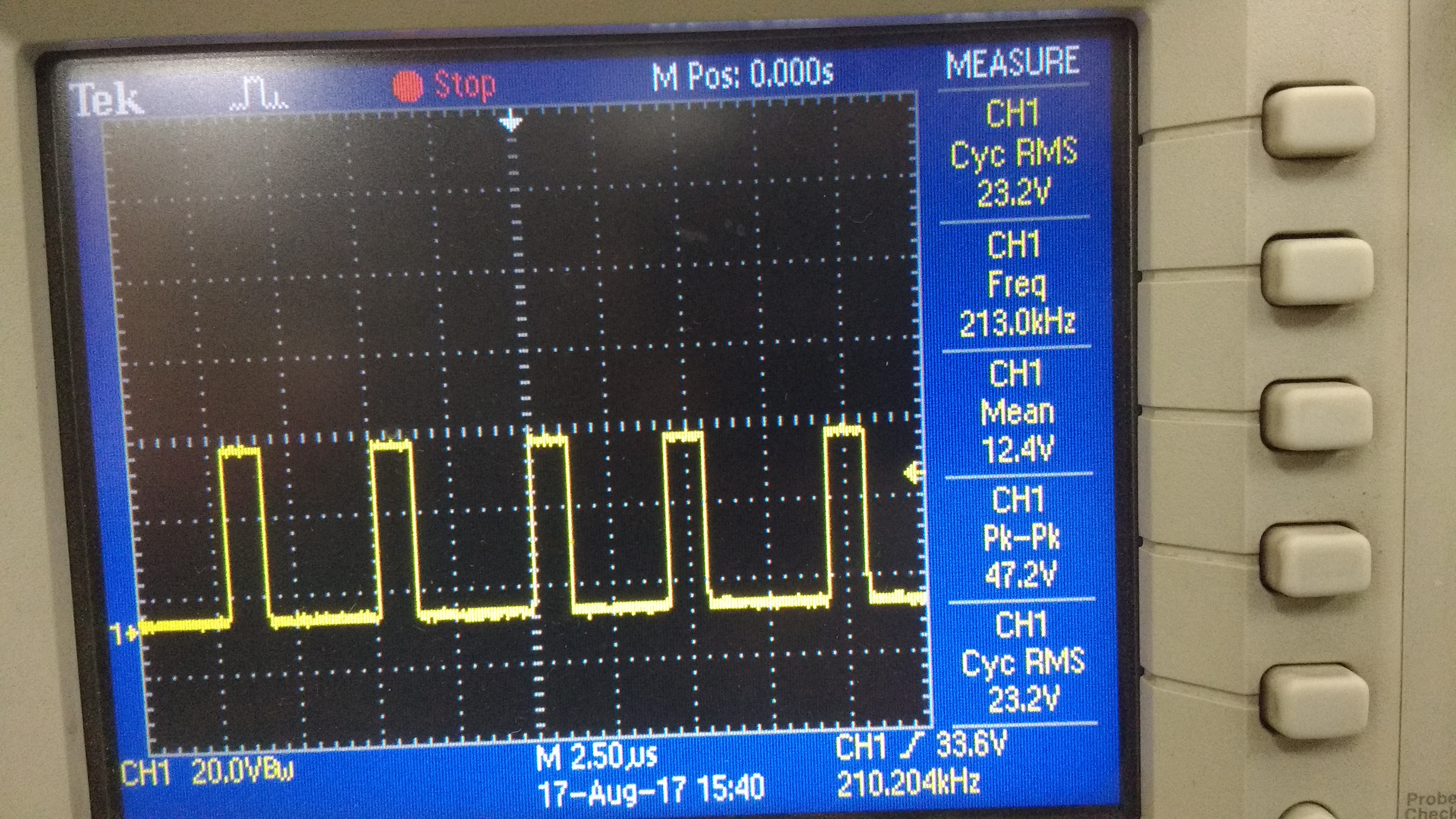
The Switch node waveform looks fine to me. It also looks stable. The likely reason why your part is failing is due to an overshoot at the input when starting up or making a fast transition of the input voltage. As I mentioned previously, should place a 2.2uF ceramic very close to the input to the device (Vin and Gnd) and also place sufficient damping at the input supply to your board where the power connects, to avoid overshoot of the input voltage due to parasitic inductances/ringing. I recommend trying a 33uF electrolytic with an ESR of ~0.5ohm as a damping cap. I hope this helps with your issue?
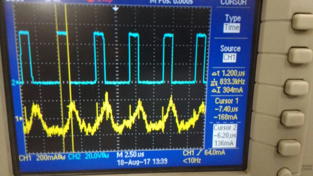
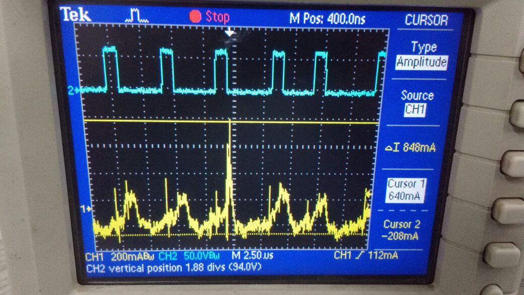
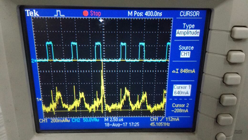
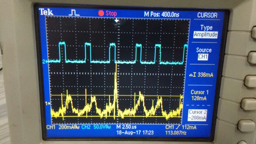
Pls refer enclosed exhibits in which we have captured various waveforms on a dual trace oscilloscope. Generally the channel/trace 2 in blue color is SW node wave form and channel 1 is inductor current waveform.
Exhibit1::: these are when V in is 36 V . Both the waveforms seem to be ok.
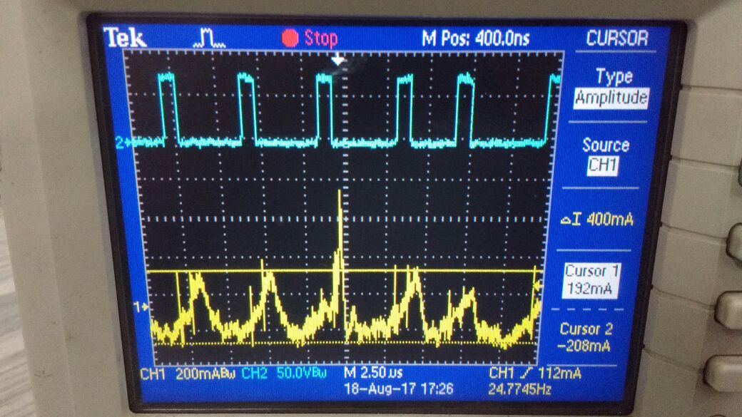
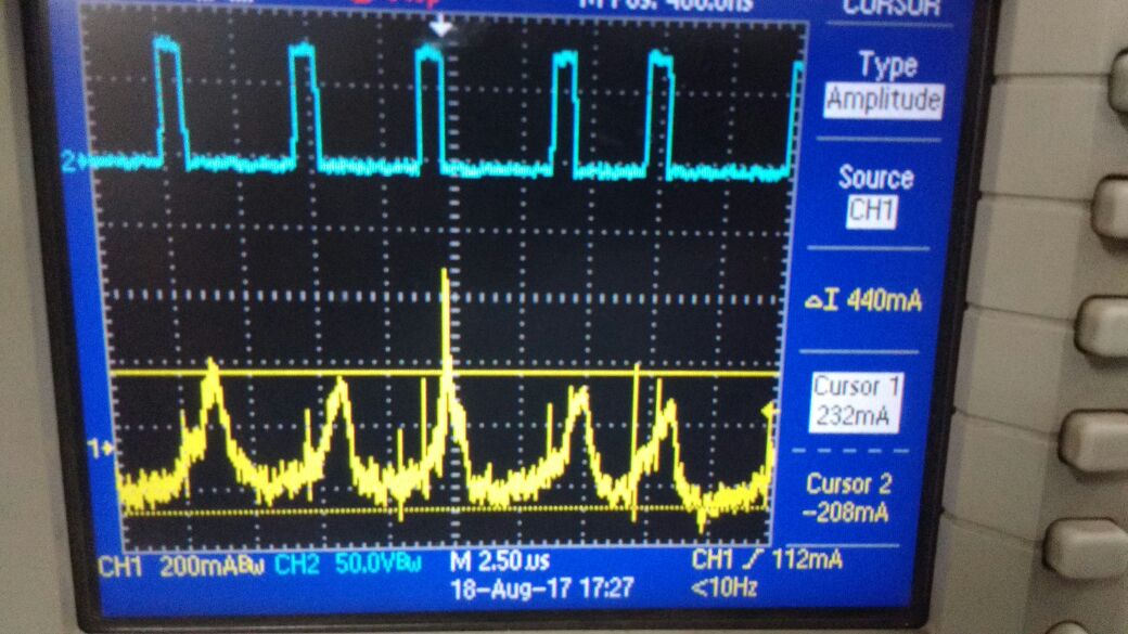
Exhibit 2,3,4:: these are when Vin is 48 V . You may see intermittent spike in Inductor current waveform .( inductor saturating)
After repeated power on's ic failed . This time output pin short . In all previous case it was input pin short.
Exhibit 5&6 ::: waveforms when Vin is 60V and 72V . The inductor current waveforms are still bad.
Exhibit 7 ::: this is for reference and comment only . This is input current from 72 V waveform . The freq is different , the current is different . We are unable to understand this .
It does look as though the the inductor is saturating, also I do not recommend using an open core inducor with a COT control architecture because COT uses a feedback comparator, in contrast to an Error Amplifier with a relatively low BW as in the case of the LM part you mentioned. I recommend using a shield inductor with COTs I suggest replacing with a shielded inductor with specs we know are suitable to determine for sure, its the inductor.