This thread has been locked.

If you have a related question, please click the "Ask a related question" button in the top right corner. The newly created question will be automatically linked to this question.

TPS54335A: About light load operation

Part Number: TPS54335A

Hi,

Let me talk about the thresh entering light load operation.
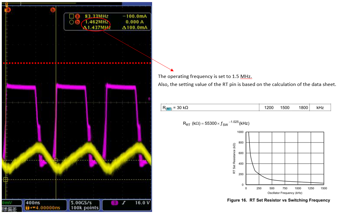
Data sheet has the following description.


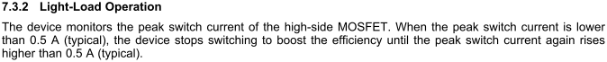
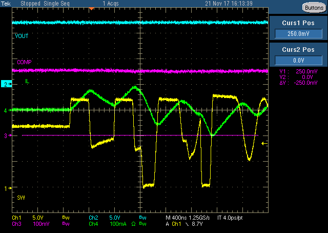
However, the actual operation is different.
Please confirm the attached file.

TPS54335A light load operation issue.pdf

I have two questions about this difference

1.Could tell me the timing to enter the real light load mode?
   Is not it actually 0.5A?
2.Could you tell me how to check the timing of entering the light load mode on actual board or EVM?

Customer wants to check the threshold to enter the accurate light load mode for low noise power supply circuit.

Best Regards,
Yusuke / Japan Disty

  • Yusuke,
    I noticed that switching frequency is about 2.5MHZ. The device frequency range is 50k-1.5MHZ. Please re-set the switching frequency (for example 500khz), test again.
  • Jason-san,

    Thank you for your response.
    The operating frequency is 1.5MHz.


    I am waiting for your advice.

    Best Regards,
    Yusuke / Japan Disty

  • Jasono-san,

    You gave me the following advice.


    I am confused.
    (Customers want to use this device at 1.5MHz.)

    Best Regards,
    Yusuke / Japan Disty


  • Former Member
    0 Former Member

    Hi Yusuke,

    "The load current at which Eco-mode™ operation begins is difficult to predict and depends on several factors that are inherent in the device design. These factors include non-linearity in the power stage transconductance, effects of slope compensation and variation in the actual COMP pin clamp voltage."

    From www.ti.com/lit/an/slva388/slva388.pdf

  • Yusuke,
    You are right, the schematic and test result is 1.5MHZ. Wrong data from my side, ignore it, please.
  • Bruce-san, Jason-san,

    Thank you for your response and support.
    I checked PDF materials you gave.
    Will the contents of this document apply to TPS54335A?

    In addition, the customer had a doubt on the contents of the datasheet.
    I got two questions from customers.


    ・It is far from 0.5A confirmed by the actual board test result.
     Could you explain this reason?

    ・Please tell me the conditions that define 0.5A(typ).
     

    Best Regards,
    Yusuke / Japan Disty

  • Hi Yusuke-san,

    I tested it again on TPS54335A EVM board under 12Vin to 3.3Vout, 340kHz, 15uH. The peak current is about 500mA when device steps into skip mode, but if the input voltage is 24V, the skip point current changes to 624mA, please see my attached. The reason why change to 624mA is because the internal slope compensation value varies with input/output voltage, fsw, or inductance, just as Bruce said. 

    Skip waveforms.docx

    Just as the description of the application note, SLVA388. the condition for entering skip mode (Eco-mode) is not peak current but the COMP pin voltage. For tps54335a, when COMP pin voltage lower down to 0.25V, the COMP pin voltage is clamped at 0.25V by internal circuit.

    BRs,

    Ryan

  • Ryan-san,

    Thank you for your kind support.
    I will report your waveform to the customer.

    I have one more favor to ask.
    Could you check the skip mode threshold with customer condition?

    Vin=18V
    Vout=12V
    L=10uH,22uH
    (Please confirm the attached file.)
    TPS54335A light load operation .pdf

    Best Regards,
    Yusuke / Japan Disty

  • Hi Yusuke-san,

    I will double check the peak current when device steps into skip mode under customer requested conditions and update the result by today, thanks.

    BRs,

    Ryan

  • Hi Yusuke-san,

    please see the attached for the peak current when device steps into skip mode. 22uH is too larger than the required inductance, the internal slope compensation already makes side-effect to the device, not recommended. All in all, peak current is not the criterion of skip mode, while the COMP pin voltage clamped at 0.25V is the right one.

    Skip waveforms -2.docx

    BRs,

    Ryan

  • Ryan-san,

    I really appreciate your sincere response for my request. 
    Let me question as to the comments on the waveform you entered.

    ”But this value makes little sense for the 22uH is much larger than the required inductance;
    the internal slope compensation has already made some side-effect to the inductor current.”

    Could you give me some more details?

    Best Regards,
    Yusuke / Japan Disty

  • Yusuke-san,
    Too large inductance would result in over slope compensation, which might be not very good for the stablity, and the inductor peak current would be varying compared with each pulse current. 10uH is enough, why need 22uH.
    BRs,
    Ryan
  • Ryan-san,

    Thank you for your response.
    I will answer your question.

    "10uH is enough, why need 22uH."

    Customers want to make PWM operation as possible.
    Because,Customers want to reduce noise due to light load mode operation.
    With that background, customers are considering 22uH.

    Could you tell me the concern of using 22uH?

    Best Regards,
    Yusuke / Japan Disty

  • Yusuke-san,

    22uH is also ok for this application, bu from cost and size side, 10uH is better than 22uH. BTW, how do customer evaluate the noise, judge by the Vout ripple or whether the device is in skip mode?

    BRs,

    Ryan 

  • Ryan-san,

    Thank you for your response.
    Customers feel uneasy about your comment below.

    " the internal slope compensation has already made some side-effect to the inductor current."
    Could you tell me the details of the relevance between the light load mode threshold and your comment?
    I want to know that the inductor is too large to happen.

    ”Judge by the Vout ripple or whether the device is in skip mode?”
    →Customers are planning to evaluate noise.
     Destruction of TPS54335A has occurred within the customer's application, and we are considering it as one of countermeasures.
     We will inform you of evaluation results and evaluation method later.

    Best Regards,
    Yusuke / Japan Disty

  • Yusuke-san,

    Yes, too large inductance has an impact on the internal slope compensation, resulting in slight stabilty issue under light load mode per my test, so 22uH is not recommended under 1.5MHz. hope to learn more about the noise evalustion menthod, waiting for your further comments, thanks.

    BRs,

    Ryan

  • Ryan-san,

    Thank you for your response.
    Could tell me more about ”slight stabilty issue under light load mode per my test”.

    For example,
    Application load is 3A at normal operation and 60mA at light load.
    In that case, 22uH can not be used.Then they can not design.
    Please tell me why the slight stabilty issue happens.

    Best Regards,
    Yusuke / Japan Disty

  • Yusuke-san,

    The inductor current is unstable slightly under this condistion, and the SW voltage is obvious various, which might be not good for the noise evaluation result. But i don't how they evaluate the noise, from function side, 22uH is accepted. If customer want use a 22uH inductor, why not reduce the switching frequency?

    BRs,

    Ryan

  • Ryan-san,

    Thank you for you kind support.
    I will check whether the customer can change the operating frequency.

    Customer response:
    When the operating frequency is reduced, ripple current increases.
    Customers want to reduce the ripple current and noise peak.

    I received the following question from the customer.

    ・Do you know the reason why the inductor current is disturbed in your wave form?
    ・Please tell me the type name of the 22uH inductor.
    ・Please clear reason not to recommend the 1.5MHz

    ・For another question:Light load mode threshold current
    Let me ask a question about how to check the current value that does not enter the light load mode.
    I think that it can be confirmed by confirming that the inductor current is not less than 0A.

    For example,
    Iload(light load mode)=1/2×⊿IL

    Is this idea and method correct?

    Best Regards,
    Yusuke / Japan Disty

  • Yusuke-san,

    Device in skip mode or not which is not decided by the peak current, when the COMP pin voltage drops down to 0.25V, the device enters into skip mode, and the voltage clamped at 0.25V. We could capture the peak inductor current when the COMP pin voltage starts to be clamped at 0.25V, the peak current value should be similar under the same input/output voltage, fsw and inductance.

    As for the inductor current is disturbed with 22uH inductor under 1.5MHz, the internal slope compensation value has an obvious impact on the inductor current under light load. The mechanism is very complicated, raltaed to the internal controll loop and logic, it's hard to make an detail explanation.

    BRs,

    Ryan  

  • Ryan-san,

    Thank you for your response and kind support.
    Let me question each of your answers.

    "As for the inductor current is disturbed with 22uH inductor under 1.5MHz, the internal slope compensation value has an obvious impact on the inductor current under light load. The mechanism is very complicated, raltaed to the internal controll loop and logic, it's hard to make an detail explanation.

    1.Does adjusting the Ccomp and Rcomp of the COMP pin affect the internal slope compensation?
       Also, Please tell me the highest possible frequency you recommend under this condition.

    2.Please tell us specifically recommended frequency.
       When considering the maximum load current, the recommended value of Lmin is follows.
       Therefore, I think that 22 uH is an acceptable value. 

    Lmin 1.31E-05 H
    Vout 12  
    Vin 17  
    Kind 0.3  
    Iout 0.6  
    fsw 1500000 Hz

     
    3.What will be improved if the operating frequency is lowered under the current conditions?
     Customers need their clear reasons and formulas to change the operating frequency.
     When the operating frequency is reduced, ripple current increases.
     Customers want to reduce the ripple current and noise peak.

    Device in skip mode or not which is not decided by the peak current, when the COMP pin voltage drops down to 0.25V, the device enters into skip mode, and the voltage clamped at 0.25V.

    1.Is it impossible to calculate the threshold of light load mode?
       Is there a method to estimate roughly?

    Best Regards,
    Yusuke / Japan Disty


  • Hi Yusuke-san,

    please see my inputs for your quesiton, thanks.

    1. Adjusting the Ccomp or Rcomp would not affect the internal slope compensation, the internal slope compensation value is constant, and designed based on the rate output current. TPS54335A could support up to 1.5MHz. if you want to use 1.5MHz, you'd better not use 22uH as the filter inductor.

    2. Please use the rate output current when calcualting the Lmin, because the internal slope compensation is based on the rate output current, so it's Lmin=2.6uH. this is a good balance between cost and performance, choose the inductance less than 10uH is reasonable.

    3. Ripple voltage is ripple current multiply by ESR, with more ceramic capacitors adding at the output side, the ripple voltage could also be reduced. the stablity has already been affected under light load on that condition, why still constant 22uH under 1.5MHz. if 22uH is perferred, please decrease the frequency a little, if 1.5MHz is perferred, please decrease the inductance.

    4. No certain formulas could be used to calculate the threshold, the best way is to measure the minimum load current when the COMP pin voltage got down to 0.25V under the actual conditions.

    BRs,

    Ryan

  • Ryan-san,

    Thank you for dealing with this matter.
    I will report it to customers.
    I would appreciate it if you could reply to my further contact.

    Best Regards,
    Yusuke / Japan Disty