This thread has been locked.

If you have a related question, please click the "Ask a related question" button in the top right corner. The newly created question will be automatically linked to this question.

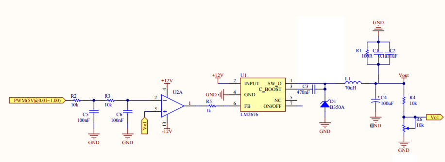
LM2676: Dears ,how to set the LM2676 as adjustable power , Vin=12V, Voutput 0.1V~10.0V,through the Voltage of LM2676 FB pin. The voltage of FB is through compare a adjustable duty cycle PWM and the LM2676 output , the problem is the Voutput will cutdown

Part Number: LM2676
Other Parts Discussed in Thread: LM2596, LM339, LM358

Sheet1.pdf

Dears ,There is a problem when i use lm2676 , I use the LM2676 as adjustable power , Vin=12V, Voutput 0.1V~10.0V, The Voutput could be adjust by the Voltage of LM2676 FB pin. The voltage of FB is through compare a adjustable duty cycle PWM and the LM2676 output , the problem is the Voutput will cutdown to 0 after 30s time ,please help to give some advice , many thanks !

  • We Will get back to you on this on Monday.

    --Ambreesh
  • Andrew,

    Can you tell us more about the conditions leading up to the failure? For example:

    • What is the load at failure? Constant load?
    • What is the ambient temperature?
    • What is the output voltage when the part fails after 30 seconds? Constant voltage?
    • Is the FB voltage steady? And how well does it regulate before it shuts off?
    • Why have you added R1, C1, C2?

    -Sam

  • Dear Sam

    Thank you for your help !

    1.what is the load at failure? Constant load?

    No-load,except R1 as dummy load.

    2.what is the ambient temperature?

    about 25°

    3.What is the output voltage when the part fails after 30 seconds? Constant voltage?

    Any constant voltages between 0.0 and 10.0, Which only can last steady only 30~50 seconds then shuts off to 0V。

    4.Is the FB voltage steady?And how well does it regulate before it shts off ?\


    The FB voltage stay steady and grdually increase with the duty cycle, the more wide the FB voltage more high ,

    5.Why have you added R1,C1,C2?

    Ressitor used as dummy load,and the capacitors as decoupling.

  • Andrew,

    R1, C1, and C2 should be on the other side of the inductor with C4. Try that and let me know if the issue persists.

    -Sam
  • LM2676_LM2596.pdf

    Many thanks,

    Actually, I've tried, remove them all, place them  in front of the inductor L1, behind the inductor, the issue persists.

    Based on LM2676,what I want to do is adjust the output voltage from 0 to 10V,  step by 0.1V.

    I learned from a product that it  uses the chip LM2676, then gives feedback signal to the FB pin of LM2676 through the output of three Parallelled dual-power supply operational amplifiers, that is +12V and -12V, as shown in the attachment . it can adjust the output voltage from 0 to 10V, step by 0.01V or 0.1V,optional. but,you know ,the circuit is too complicated, the cost of components is high.So I built a circuit by myself that using a dual power operational amplifier to provide feedback to LM2676. After all, I just need to output voltage can adjust from 0 to 10V.

    Also, in another product, someone with a chip LM2596 can adjust the output voltage, from 0.3 to 12 V,step by 0.1 V, as shown in the attachment .

    The regulation of the output voltage of the two products all  beyondthe range of  their chip specification declared in 1.2V to 37 V.

    as you can see, the output voltage regulation, from almost 0 v to 10 v, is realizable. the biggest problem is that it cannot last too long, I don't know what causes the output voltage  suddenly shuts off to 0 v, under the normal operation of the input PWM signal.

    My english is poor,I wish  have made myself understood,

    many thanks again.

  • Alfred,

    Thank you for the information.

    The most likely issue is that the part is heating up and shutting down. Not much else would work for 30 seconds, then all of a sudden stop. This could be because of the capacitors on the SW node, but you said you tried it both ways. Please measure the temperature of the top of the IC during operation.

    -Sam
  • Thank you for your patient reply.

    One heatsink is applied,

    I measured the operating temperature of the IC according to your suggestion, see the attachment.

    LM2676_Temperature.pdf

  • Alfred,

    Is this in no-load condition? The IC should head up more than 0.1 degrees in most conditions. How were you measuring temperature?

    Can you try removing the heatsink (just unscrew and bend the IC so it's not touching) and see if it takes less than 30 seconds to shut off.

    I trust that you're testing this properly but I want to make absolutely sure of this before we move on.

    -Sam
  • There was an obvious mistake in the previous measurement, and it has been corrected. According to your suggestion, I have retested it in no-load condition. See the attachment for details.

    I sincerely thank you for your help

    4101.LM2676 debug.pdf

  • Alfred,

    I'm sorry, I missed something. I was still thinking about the first schematic on the original post "Sheet1.pdf." The schematic on your attachment has C7 which turns the op amp circuit into an integrator (hence the ramp on FB). Do you see this issue when you remove C7?

    -Sam
  • I built a test circuit based on LM2596T-ADJ . The same problem still exists, that is the output voltage will shuts off to 0V after 30~50 seconds' operation.

  • when remove C7(100nF/50V),the output voltage is adjustable, the issue persists
  • Alfred,

    What is the voltage on the FB pin when you see the output drop to 0V?

    -Sam
  • with C7," ..... Once set the output voltage,even one step 0.1V,on the small touch screen,the FB pin voltage dropped immediately from 12V to about 1.46V. In subsequent debugging,that is setting the output voltage to 0.1~10V,the FB pin voltage is maintained at this level. Unless the output voltage shuts off to 0V,the FB pin voltage drop to about 0.61V,see fig Fig 1.2.1c.  ......"

    without C7, see the attachment.

    LM2676-FB pin Voltage.pdf

  • Alfred,

    There is more than one schematic (confusing) so let's agree to talk about this one from now on (below).

    If you are using the -ADJ version, the FB pin should always stay at 1.2V. The IC will increase and decrease SW duty cycle to get FB to 1.2V. You can check this by seeing FB and SW_O on the same scope shot.

    It looks like your pictures show FB going down to -12V. This should not be done and may damage the part. You may be able to prevent this by changing the -12V supply to GND, but even in normal operation this should not happen anyway. Please check pins 1, 2, and 3 on the op amp to make sure this circuit is behaving the way you expect.

    -Sam

  • I have measured the FB voltage both withC7 and without C7.

    now,I'm trying to replace an operational amplifier with a single power supply,that is LM339.

  • Alfred,

    LM339 is a quad comparator. Is that part number correct? I would not advise to replace the op amp with a comparator.

    -Sam
  • I made a mistake, it should be LM358.

  • Okay, let me know if you have any questions about the LM2676.

    -Sam
  • The issue persists.
    I used the LM358,and the output voltage can be adjusted from 0 to 10V, but it can not last more than 1 minute.
    There is a small change here, and the FB voltage is maintained at about 1.2V during the whole operation,it seems like a small step forward?
  • Alfred,

    You changed the op amp and the performance improved. This indicates that the op amp circuitry may be causing the issue.

    Again, if the SW node and FB node are correlated (when FB decreases, SW duty cycle increases and when FB increases, SW duty cycle decreases) then the LM2676 is working properly.

    -Sam