This thread has been locked.

If you have a related question, please click the "Ask a related question" button in the top right corner. The newly created question will be automatically linked to this question.

LM2776: Charge pump does not output the good voltage.

Part Number: LM2776
Other Parts Discussed in Thread: LMH6702, ADC08200

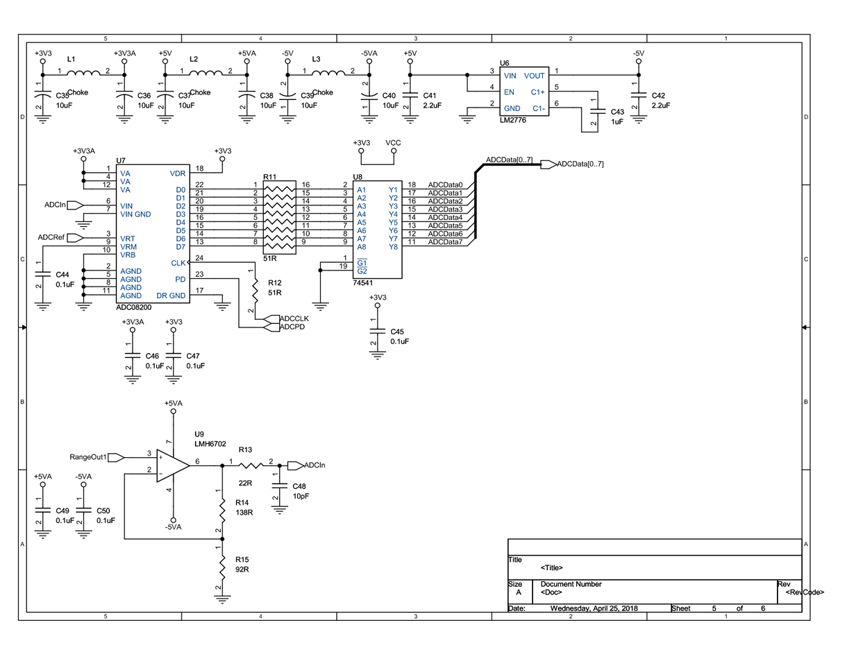
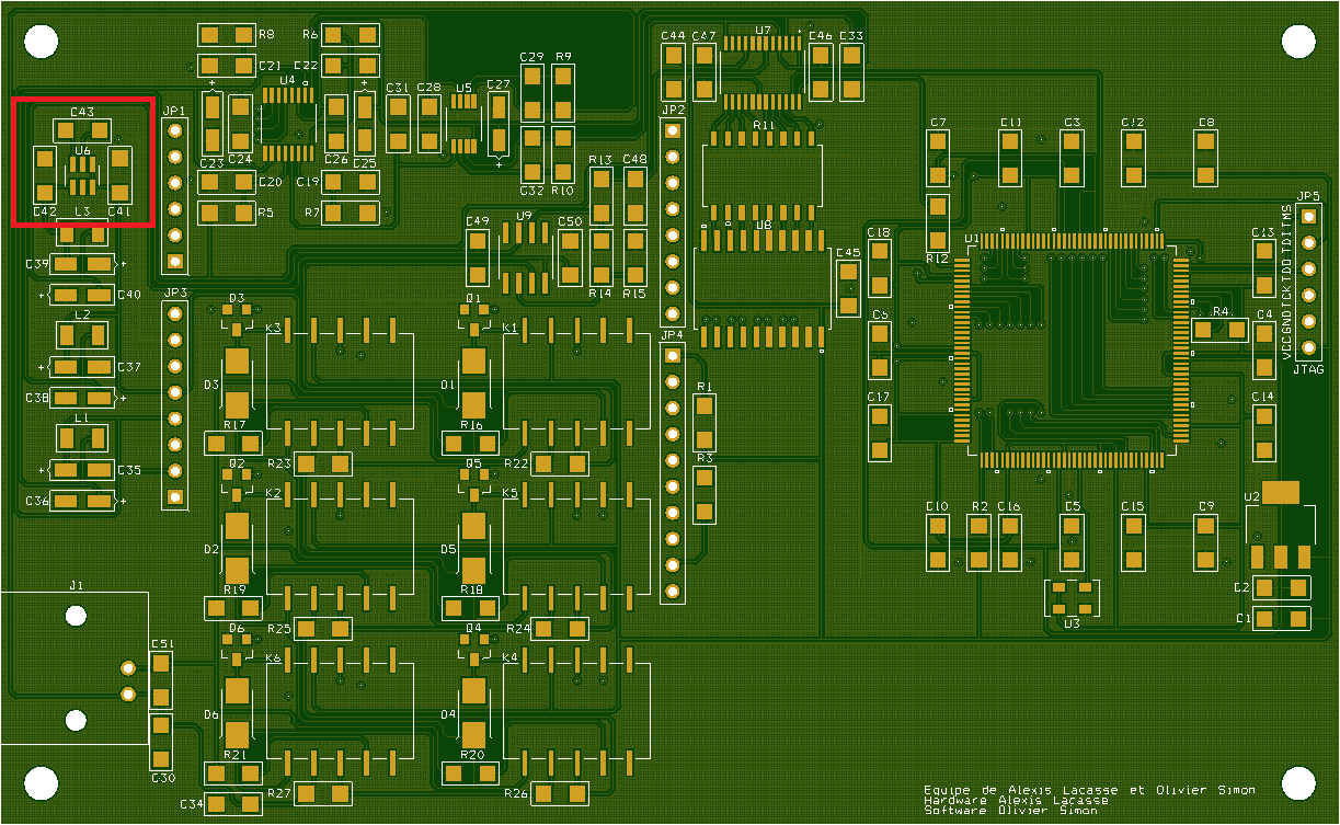
I have an operational amplifier (LMH6702) in my circuit that need to be powered with +/- 5V. Since I don't have a power rail of -5V in my circuit I used the LM2776 charge pump to obtain it using the +5V power rail available in my circuit. The LM2776 is not outputting the -5V that I was hoping for. The output is -1.76V it is not enough to power the operational amplifier. I followed the typical application of the LM2776 datasheet (http://www.ti.com/lit/ds/symlink/lm2776.pdf) using the same capacitor value. I am wondering if the 10uF tantalum capacitor (C39) on the -5V rail is causing this problem. The L3 choke is replaced with a 27 ohm resistor.
Excuse my english I speak french.

  • Hi Alexis,

    Can you send a waveform of Vin, C+, C-, and Vout (all waveforms measured on the same net as the IC's pins and not after any resistors, etc.)?

    It's a little difficult to read the layout, but I do not see a short/direct connection to the GND pin from the input cap. This is required for most any switching converter.
  • Hi Alexis,

    Were you able to solve this issue or capture a waveform?
  • Hi Chris,

    Sorry for my late response, I kind of find a fix for my issue. I used another 5V power source. Initially my 5V power source was comming from one of the USB port of my PC, now it is comming from a variable lab bench power supply. My PCB require around 500 to 600 mA, since typical PC USB port can only supply a maximum of 500 mA it might be the issue. I'm not sure of the quality of the USB cable I used, I haven't mesure the voltage drop across the cable. Also, the output voltage of the variable lab bench power supply I use rise kind of slow when turned on. I noticed that when the variable lab bench power supply is turned on (output stable at 5V) before I connect its output to the PCB I still have the same issue. I need to connect the output of the variable lab bench power supply to the PCB before it is turned on in order to make this work. I know that I haven't really solve the issue but it will get the job done. This is for a school project and time is getting short I didn't want to take to much time on this issue since there is still a lot of work to do. The project I am working on is a portable digital storage oscilloscope with 6 ranges (1Vac, 5Vac, 10Vac, 25Vac, 50Vac, 100Vac) using a ADC08200, STM32F746 Discovery kit and Spartan 6 FPGA XC6SLX9. I had a total of 12 week to do this project and there is only 1 left.

    Thanks

    Alexis Lacasse