This thread has been locked.

If you have a related question, please click the "Ask a related question" button in the top right corner. The newly created question will be automatically linked to this question.

VUSBIN.CAPOUT of TPS65951

Other Parts Discussed in Thread: TPS65951, TPS65950, DM3730

Hello Everyone,

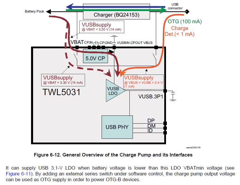
I have a question regarding the VUSBIN.CAPOUT with TPS65951 chip. This pin is a new one comparing to TSP65950. Is there a register controlling it for example the direction of this pin? I guess by default it is VBUSIN, and it changes to CAPOUT when a USB memory stick is inserted. But does the software control it? If so, how to do it? There is no register associated with this pin.

Right now, VUSBIN.CAPOUT pin is not connected to VBUS and OTG works only when the device is connected to PC. If I insert a USB memory stick, I can see an interrupt and the driver reports "VBus Error - OTG_HandleVBusError to be implemented".

I am using Flahsboard2 with Windows CE OS.

Any help is appreciated.

Thanks,

James

  • Forgot to mention that VBAT is connected to power supply. Battery is not used. So we don't need to worry about VBAT voltage level.

    The register VUSB_DEDICATED1 is set to 0x14 which means VUSB3V1 = 3.10V and VUSB3V1 VDD is switched to VBAT.

    Thanks,

    James

  • I would like to get some clarification on TPS65951 USB OTG transceiver.

    1. Should pin VUSBIN.CPOUT connect to VBUS ? If yes, why?

        If we select VBAT as the source of VUSB3V1, can we disconnect VUSBIN.CPOUT from VBUS?

    2. If VUSBIN.CPOUT and VBUS pins are not connected, and DRVVBUS in OTG_CTRL is set to 1 (I verified that by dumping the OTG_CTRL register value via I2C), why the VBUS is still 0V?

    3. Is there any porting guide or instruction to help us porting device driver for TSP65950 to TSP65951 to make USB otg work?

    Currently I am using PTI Flashboard2, with Windows CE. The device driver for PMU USB otg is the same as the one for TPS65950. I have tested TPS65950 USB otg driver with Mistral EVM by modifying the board to use PMU USB otg instead if ISP1507. Both host and device worked fine.

    Right now, with Flashboard2, only activesync works.

    I need some help to make otg host work.

    Regards,

    James

  • James,


    VUSBIN.CPOUT  must be connected to VBUS if you want the TPS65951 internal charge pump supplying VBUS in OTG HOST mode. The internal charge pump is connected on this pin, not on VBUS. it has been done this way to easily use an external Boost for the OTG 5V generation in case more than 100mA are needed.

    The DRVVBUS control the charge pump which is connected between CP.IN and VUSB.CPOUT.

    Please have a look to the TPS65951 Datamanual chapter 6.1.16 and 6.1.19.

    http://www.ti.com/lit/gpn/tps65951

    Please also check this post regarding the VUSB_DEDICATED1 register

    http://e2e.ti.com/support/power_management/pmu/f/43/t/199520.aspx


    regards,

    Alexis

  • Hi Alexis,

    Thanks for your answer.

    The reason why we disconnect VBUS from CPOUT is that there is 3.3V on CPOUT. When we connect VBUS to CPOUT, VBUS will have 3.3V also which generates interrupt to the processor with STS_VBUS set to 1 in STS_HW_CONDITIONS register. But there is no device plugged in OTG port.

    With TPS65950 used in Mistral EVM, the VBUS is 0V when USB OTG is in b_device_idle state. The device driver works fine.

    Could you tell us why there is 3.3V on CPOUT pin and is it possible to disable the voltage when OTG is in b_device_idle state. By default when there is no device plugged in the OTG port, the OTG state should be b_devcie_idle. Currently the CE device driver is confused by the 3.3V on VBUS.

    The VUSB_DEDICATED1 register is set as 0x14 which means VSEL = 000 and USBIN_SW = 01.

    Thank you very much for your support.

    James

  • Soory,

    My answer was not accurate enough.

    As explained in previous post, Charge pump functionality and block diagram is detailled chapter 6.1.19

    You can  see that when the VUSB.3V1 LDO is supplied through VBAT, VBAT and VUSBIN.CPOUT is connected to VBAT through an internal switch controllled by VUSB_DEDICATED1 register. It's the reason you see 3.3V(VBAT) on VBUS, triggering the VBUS presence comparator.

    The first purpose of the charge pump is to supply the VUSB.3V1 LDO in case the battery voltage goes bellow 3.3V. If you want the charge pump to be used for OTG, you need an external switch between VUSBIN.CPOUT and VBUS as explained just bellow the figure 6-12.


    TPS65950 does not have the same Charge pump architecture. The Charge pump is directly connected to vbus. Drawback is that when you want an external boost to provide the OTG 5V, there is a conflict with TPS65950 internal charge pump which is automatically enabled by USB state machine in the host processor through ULPI.

    regards,

    Alexis

  • Hi Alexis,

    Thank you very much for your prompt response.

    Now we are clear where the problem is. The original hardware design put a zero ohm resistor between VBUS and VUSBIN.CPOUT. We suspected something wrong over there and that's why we removed that resistor to leave VBUS and VUSBIN.CPOUT disconnected. We will put a switch instead of zero ohm resistor and control the switch by a GPIO pin via software and test it.

    Thanks again and best regards,

    James

  • Hi Alexis,

    We added a switch between CPOUT and VBUS and controlled the switch by software.

    By default, the switch is off which means VBUS is not connected to CPOUT. The voltage on VBUS is 0v and voltage on CPOUT is 3.3v.

    The switch is turned on in function IsBDeviceConnected() when B device is connected. If there is a disconnection, the switch is turned off to bring back to the default state.

    After the modification, the activesync works fine. But if I inserted USB memory stick, the interrupt is generated and the driver detects that B device is connected and turns on the switch. However I get error message "VBus Error - OTG_HandleVBusError to be implemented". I measure the voltage and both CPOUT and VBUS are 3.94v. It seems that charge pump is turned on and passed to VBUS (since the switch is on). But how come the voltage is 3.94V instead of 5V?

    Could you give me your insight on this issue?

    Best Regards,

    James

  • Hi James

              I use 3715+65951,  and meet the same issue. Did you finish this problem? Ths.

  • Hi James,

    I'm also facing similar problem like you.

     I'musing DM3730  with TPS65951 PMIC. I can see the USB client working properly in bootloader. But in OS level I'm facing issues in OTG client.

    I can see the following prints, ULPI registers can't be accessed.

    ####### FAIL to read ULPI Reg, Control = 0x5
    Attempt Recovery Procedure 1
    Assign ULPI signals to GPIO
    Restore ULPI Signals

    I can see from the forum, some others also facing similar issue. But I can't find any solution for that. Did you face similar problem on OTG client side? or is there any specific configuration need to done on TPS65951  PMIC side other than TPS65950?

    Also do you solved the OTG host issue ?

    Thanks,

    Jeslin.


  • Hi Guys,

    I have solved this problem. A switch should be added between CPOUT and VBUS and it should be controlled by a GPIO pin. Software needs to toggle this pin to turn on/off the switch. By default, the switch should be off which means that CPOUT is not connected to VBUS. The OTG state should be b_idle. When a USB memory stick is plugged in, an interrupt will be raised and driver should check which device is connected. If the ID is grounded, driver knows a USB B device is connected and at this time software should turn on the charge pump and connect CPOUT to VBUS. you also need to change the power source of 3V1 to use VBUS. After you unplug the USB memory stick, the driver should restore back to b-idle by turning off the switch.

    Good luck,

    James

  • Hi James,

    Thanks for your concern. For me the USB Client itself not working properly in OS level. We have a switch in the hardware between CPOUT and VBUS and the switch is in OFF state. For us ID pin is in floating state. When I connect the device to the PC It shows above ULPI error messages(mentioned in previous post). To recover from this error or to avoid it, Is there any PMIC configuration need to be changed (now I'm using the same configuration as such TPS65950). Or else any hardware limitations are there between TPS65950 and TPS65951?

    Once I make the OTG client (active sync) work, then only I can try for OTG host (memory stick).

    Thanks in advance

    Jeslin Paul J.

  • Hi James,

    Can you provide your working PMIC dump for TPS65951? It will be really useful for me and many who got stuck with this same problem.

    Thanks in advance,

    Jeslin Paul J.

  • Hi All,

    I'm using TPS65951 as a power supply to Processor DM3730. I have no need to use the USB functionality of the device including VBUS. Please let me know how to use the IC in this mode, as the 'Unused state' of the USB PHY pins is mentioned as 'Not Applicable' in data manual. Also let me know whether VBUS is necessary for operating the device even when only power providers are being used.

    Regards,

    Anindya Chitta Bagchi