This thread has been locked.

If you have a related question, please click the "Ask a related question" button in the top right corner. The newly created question will be automatically linked to this question.

TPS65910A3(1) Wrong Voltages

Other Parts Discussed in Thread: AM3352, TPS65910

Hello,

I recently created a custom board based on the AM3352ZCZ, with DDR3 so I selected the TPS65910A3 as the PMIC (I was mainly basing off the SK.)  I basically created a straight copy of the SK design, with three changes:

1) I did not use an external RTC LDO, I just wired the VRTC output of the PMIC to the AM3352, since I figured I wasn't going to use the PMIC in RTC only mode anyways.  I got lucky here because I got mixed stock of the PMIC from TI samples, and ended up wtih the -A31 on half the boards.  So, I'm changing the BOM to specifically call out the -A31 part from here forward.

2) I did not wire RTC_PORZ to anything.  I know now this is a problem, but at the time I didn't figure it would hurt since I wasn't using RTC anyway.  The PMIC enable still goes high (VRTC level) and turns on the PMIC.  I will design in the delay circuit next board spin.

3) I wired INT1 and SLEEP to the AM3352, figuring it can't hurt if I ever want/need to use them.  I also connected both sets of I2C pins.

My problem is that the voltages on the PMIC all come up higher than expected:

VRTC - 2.6V

VDD1 - 1.5V

VDD2 - 1.5V

VIO - 2.6V

VDIG1 - 3.0V

VDIG2 - 2.29V

VAUX33 - 3.77V

VMMC - 3.77V

VDAC - 2.29V

VPLL - 2.29V

VAUX1 - 2.29V

VAUX2 - 3.77V

I isolated the PWRHOLD on the PMIC from the PMIC enable on the AM3352 and reapplied power and still get VRTC at 2.2V.  The only thing I could find is that a couple other people had the same problem, and the only solution I found was that someone had BOOT1 tied to VDAC instead of VRTC.  On my board BOOT1 is correctly tied to VRTC.

I know that my RTC_PORZ is not correct, but it's the only thing I can find that is fundamentally "wrong" with my board vs. any of the reference designs.  Could this really have an effect on the voltage levels the PMIC comes up as?  Perhaps VRTC coming up at 2.6V, then the PMIC enable being pulled up to 2.6V instead of 1.8V zapped the PMIC somehow?

I have verified that all parts and connections on the PCB match the schematic for good measure.

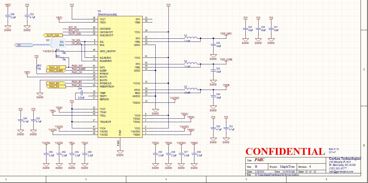
(don't worry about the confidential note, this section is just a copy of the reference design which is public domain)

Thanks in advance to anyone that can shine some light!

Adam

  • I just got a couple boards with the TPS65910A3 part (opposed to -A31) and get the exact same thing.  There goes my theory that I somehow got a batch of unprogrammed parts.  Oh well, back to the drawing board.  I'm still completely stumped.

    Adam

  • I found something else interesting.  I disconnected VRTC from the CPU on the CPU side and did a quick power up.  The voltage jumped to the usual 2.6-2.7V but when I turned the power supply off, the voltage on VRTC slowly fell, now that it didn't have a load but still had the 2.2uF cap, when it got to around 2.1 volts it snapped to 1.8V and held there for a second then dropped off as the voltage kept falling.

    I turned the power supply down to 4.0V instead of the usual 5.0V and it did the exact same thing.

    No one has any ideas?  I've been at this for almost 4 days now and can't figure out what the hay is going on!

    Thanks,

    Adam

  • Got it!  I didn't have REFGND connected to ground, duh.  I completely missed it in the SK schematic, and figured REFGND was tied to GND internal to the part.

    Now the only thing I see is VRTC still comes up at 2.3 volts for some reason, and VDIG1 is 2.6.  VRTC I believe should be 1.8V no matter what, correct? VDIG1 does show a max of 2.7 in the data sheet so it seems ok but on the SK (and my board) this is wired to VDDSHV1 on the AM3352ZCZ which in the data sheet says it wants 3.3V.

    Literature Number SWCS093A actually shows that both VDIG1 and VRTC should default to 1.8V.  Anyone have any ideas about this?  This board was no powered up without REFGND connected to GND.

    Adam

  • One more piece of info, if I ground PWRHOLD and turn the PMIC off, VRTC drops to the expected 1.8V.  As soon as I release it VRTC jumps back to 2.3V and VDIG1 goes up to 2.6.

    This is driving me crazy!

  • Well, I saw on basically every other reference design except the SK that VDDSHV1 was tied to VMMC or VAUX2, both of which are 3.3V.  So, I tied it to VMMC instead of VDIG1 and sure enough, VDIG1 dropped down to the expected 1.8V.  VRTC remains at 2.3V but I'm suspecting that has something to do with VDIG1 voltage being out of whack.  I'll mod up another virgin board and see what happens.

    If anyone from TI is reading (I feel like I'm just talking to myself here) why is the AM335x SK different to all the other designs?  It appears to be wrong/non functional but I'm sure there are plenty of working SK's out there.  Maybe the schematic is old?

  • Ok so I modded up a fresh board that had never been powered up and VRTC still comes up at 2.3V!  What the heck is going wrong? AHH.

    I confirmed with U-Boot that the RTC module on the previous board isn't working, I suspect it's blown up from the 2.3V.

  • I know it is an old thread, but I had the same problem and solved it.

    The TPS65910's CLK32KOUT is in VDDIO power domain while the AM335x's RTC_XTALIN is in fixed 1.8V domain. If you use VDDIO=3.3V and connect these two pins together, it pulls up VRTC's voltage to ~2.4V.

    I hope this will help someone.

  • Please click verify to close the post if this issue is resolved, If not please let me know.


  • Hi Adam,

      Have you fixed this issue?

    My customer has the same issue. And the schematics they did is the same as starterkit's.