This thread has been locked.

If you have a related question, please click the "Ask a related question" button in the top right corner. The newly created question will be automatically linked to this question.

LMZM23600: Distributed Sensor Network Stability

Part Number: LMZM23600

I am looking at using the LMZM23600 modules as a primary step-down stage in an industrial Modbus networked devices. This type of network has a central 120VC to 24VDC switch mode power supply that is then used to supply a long chain of devices that are placed about 150-200ft apart. Each device taps into the continues run of power cables.

With this topology, the supplied voltage is progressively diminished at each node and the total current is a sum of all the downstream nodes. The number of modules is normally limited by the drop out voltage at the end of the line, but can be in the order of 20 devices with 0.5W to 2W each. 

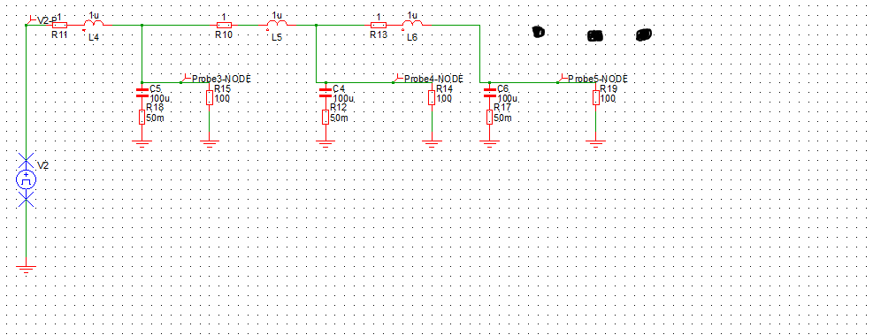
I was reading in the datasheet section 10.3.2 Stability, that there is a need to dampen the circuit with respect to the line resistance and inductance. But in my case, the R and L are different for each node on the network, with the closest module to the power supply having much lower values than the node at the end of the line. Tuning these parameters is not possible during installation so I need some way of optimizing the network as a whole. Using large input capacitors places a large demand on the central supply. 

Is there any existing models of such networks that can be used to analyze the transient behavior of such a system.

Any help to get a better handle on this topic is appreciated.  

  • Hi Lily,

    There currently is no model for this network. However I do recommend using a simulation tool like SIMPLIS to test line transients on. Perhaps run a pulse wave to see how to delays in the system affect each power module and a current probe at the central supply to see how much current is drawn during start-up. 

    From the application description you sent, it sounds like the power modules each have different lengths to the central supply. The long cables are represented as a RL series network. You would have to measure the resistance and inductance of the cable you are using as the power path to the LMZM23600s. Also, you would need to change each Rload to the expected load current you will have on each regulator. I've attached an image of what I think the simulation would look like as a starting point to understand your circuit. The circuit should have a total of 20 RLC networks to simulate your application.

    Regards,

    Jimmy

  • Thanks, Jimmy,

    Your model suggestion is very similar to what I was thinking. I will give that a try.

    Regards,

    Lily  

  • Hi Lily,

    Is there anything else you need help with? Unfortunately as I've stated above, we don't have any way to model your power supply. We have Webench model simulations for the LMZM23600 and what happens downstream from it.

    Regards,
    Jimmy
  • Hi Jimmy,

    I need a bit of time to sort out a proper modeling tool, but I have enough to go on for now.
    Thank you for your help, and I may ask follow up questions if we run into issues.

    Regards.

    Lily