Because of the holidays, TI E2E™ design support forum responses will be delayed from Dec. 25 through Jan. 2. Thank you for your patience.

This thread has been locked.

If you have a related question, please click the "Ask a related question" button in the top right corner. The newly created question will be automatically linked to this question.

LM2576/2596-ADJ noise problem

Other Parts Discussed in Thread: LM2576, LM2596

Hello,

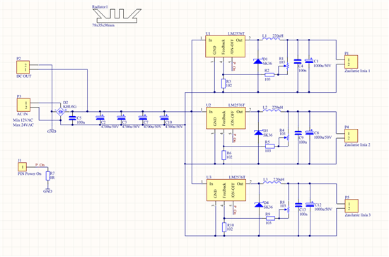
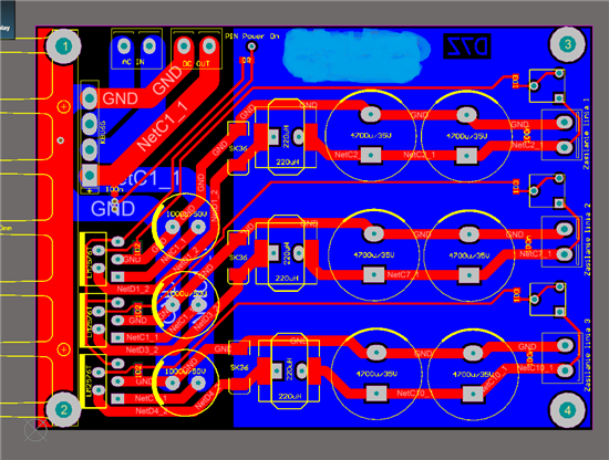
I've designed a power supply unit on LM2576-adj. There are 27V DC on the input and on the output I've set 20V. There are 3 LM2576's connected parallel after greatz bridge together with 3 electrolitic capacitors 4700u. On the output there is coil 220uH, 3A shottky diode and 1000u electrolitic capacitor. On the PCB there is 3 IC mounted to the heat sink.

 The problem which I receive is that when I connect load with more than 1A current, one of the IC's which is in the middle gave me a noise on the otuput approx 60mVp-p and about 3kHz freq (similar to saw shape). I can hear this in speakers in my audio system. On the rest two IC's I doesn't hear anything. Could you advice what can cause this. I've already exchange all the parts and it doesn't help. 

The PCB board is already updated according to schematic diagram (the wire layout is old). Below is the diagram and pcb board. 

Best regards,

Pawel

  • It could be many things.  I have the following comments:

    1.  A value of 1000uF on the output seems very large to me.  It could be that you have a stability problem.  Did you check this on Webench?

    2.  It could be an interaction between the regulators.  Try turning on one at a time and load them to see if they are OK.

    3.  A small ceramic capacitor across the input pin and ground of the regulator may help; from 1uF to 10uF is a good start.  The large electrolytic cap is not a low  impedance  at high frequencies.

    4.  The feedback components, resistors and trimmer, should be much closer to the regulator.

    Frank D


  • Hi Frank,

    Thank You for advices. I've played with couple of different capacitance on the input and output and the conclusion is that, it looks better when the output capacitance is about 100 - 220uF.

    Ceramic capacitor on the input is making more noise.

    I'am able to make a "quite" output on one IC, when I connect a polygon on the bottom side of the pcb only in one point ("-" of output C). But when I connect second IC then on one of the IC output, noise appear again.

    Finally I was able to make a noise free output on both IC but only in one output voltage and current set. If the load current have changed or voltage, then noise is comming back and also sometimes 50Hz noise from the supply net appear. 

    It generally looks like something is not stable. How I can get stable state if the current load will be changing (0,5 - 2A) an I need to have an output voltage setable (16-22V)??? 

    Or maybe I should looks for another IC? 

    Pawel

  • The best way to check stability is with webench.

    Frank D


  • Hi,

    I've choose components according to Webench for couple of different currents and it is still the same. When I set the R feedback value to have noise eliminated and when I change the load the noise is coming back :(.

    Do somebody have the same issue with no adjustable version of LM2596 (ex. LM2596-5) ???

    Regards,

    Pawel

  • Hello Pawel,

    It has become a little confusing. In your first post you mentioned you had 20V at the output. But in your latest post it sounds as if you are using a 5V part. Would you please confirm what is your load requirement (Vout and Iout)?

    Additionally, your layout does not seem optimized. You should have a small Cin bypass cap very close to the input pin and the trace to the input should not be thin and long. The Swich node trace also should not be thin and long. Ideally you want a short fat polygon for the switch node. The feedback trace should not run very close to the noisy switch node. If you have a 50Hz noise passing through, then you need an input filter. I am attaching a presentation that we have. It talks about mitigating EMI by following good practices in board layouts and also has equations and spreadsheets to calculate component values for the filter. If you follow the instructions, it would be very beneficial. I hope this helps.

    4643.PCB layout and EMI mitigation.pptx

    Regards,
    Akshay 

  • Hello,

    Isn't that true that LM2576 series are not designed to share load ?

    Thanks

  • Yes, that is true.

    FD


  • Hello

    The ppt contains information about reduction of EMI noise by using correct techniques of pcb designing but does not contain any information about removal of 50Hz noise. I wanted to know how one could remove the 50Hz/60Hz noise from the power supply. RC-filters is one of the methods but I wanted to knowif there are any special TI ics designed to remove this noise?

    Thanks 

    Shravan Raghu

  • The bandwidth of the regulator should be enough to filter out 50Hz/100Hz ripple from the input.

    It may be that your layout is causing a lot of this noise.  The large 100Hz current pulses from the input capacitors has to flow back to the bridge.  It looks like in your layout this could be causing a ground bounce.

    FD

  • Hi there. Was trawling the net for info on smps ic,s when i came across the prob faced by Pawel and felt i could add some to it. Still the points mentioned by them are pretty valid.Lm2576/96 have very good and extremely agile protection circuitry that takes care of many complications arising due to many variables. Whilst the pcb appears to have looked into many common issues, I feel part other reason of why the central unit is misbehaving is probably the "mixure" of three different frequencies of these three units that are working so close together esp with the sensitive f/b circuitry in close proximity with one another.I had read somewhere that this could be solved by making sure that all regulators ( in this case L4960, also another Gr8 switcher which had provision for connecting the osc of other switchers nearby to run together at the same freq.) it is frequently assumed that the ic,s run on the same freq and they will all "sing" together. This is wrong esp with the powers and close proximity. You don't have to be the conductor of the Philharmonic Orchestra to conclude that small differences in of the fundamental frequencies of each of these switchers will spawn a huge harvest of sums and differences of these notes which could easily create a complex cacophony instead of a single assertive no nonsense tone that should have been just the stuff that the doctor ordered . The opt caps also appear close by... be too large. Anything below 500uf should suffice(use at least 35/50v types mounted close

  • Sorry... had to conclude as i want able to type much longer as the width of the post started dropping alarmingly . Well one portion was that there was the ac mains ripple that was coming through.I remember this was a very common problem in the olden days of radio reception esp on the Mw and Sw bands. This used to cause an annoying hum when the stn was tuned in. This was taken care of by adding a ceramic cap (usually .01 to.1uf depending on the inclination rather than type of the radio in question ) across the power diodes in the power supply. I hope this takes care of burgh the problems that you seem to be battling with.Also I suspect that the series choke that you are using isn't capable of supplying the desired power. Try to change it and you should have some Improvement.... Do let me know the final outcome..