This thread has been locked.

If you have a related question, please click the "Ask a related question" button in the top right corner. The newly created question will be automatically linked to this question.

LMZ31707: Output voltage error

Part Number:

hello All,

We have a problem with a 12V to 1.8V design using the LMZ31707.

Below I will share a detailed description of what we see, signal measurements, etc.

Any assistance will be highly appreciated.

See below our design:

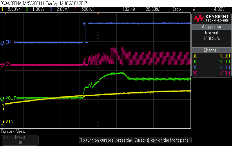
We are unable to get the required output. Instead we get ~1.2V.
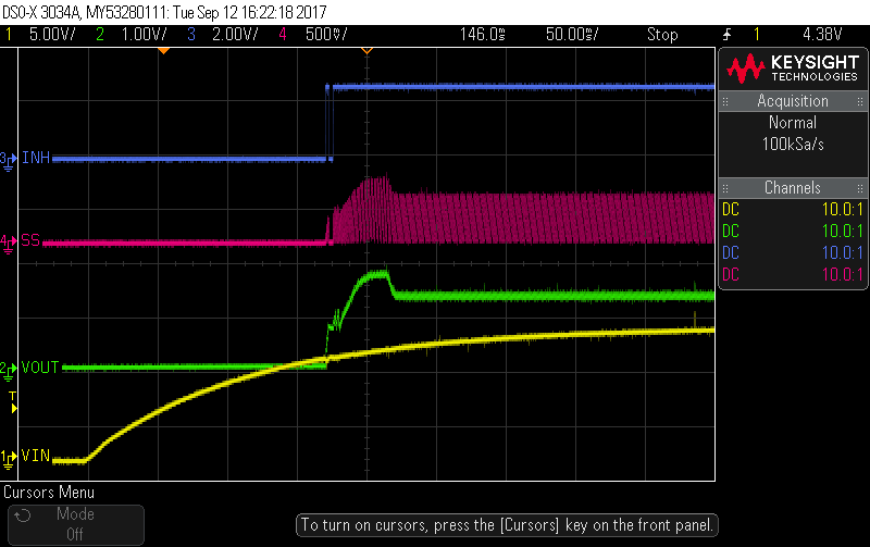
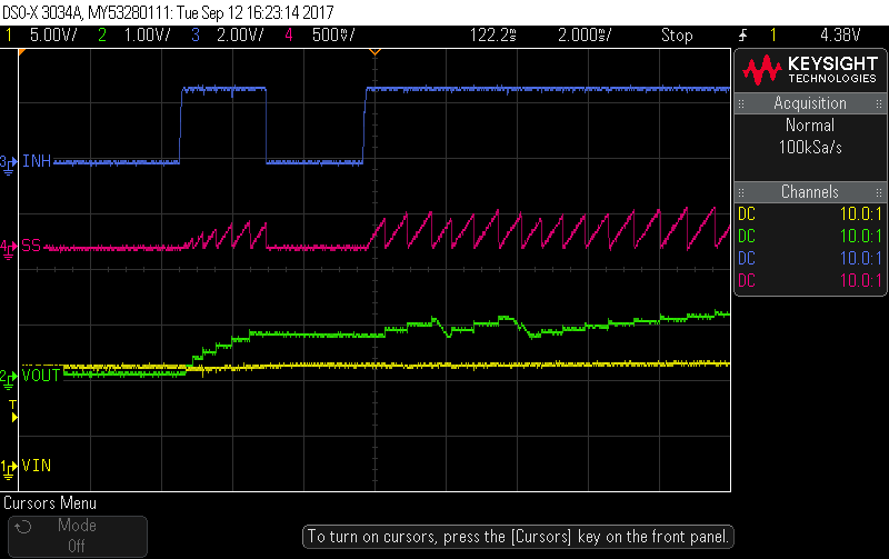
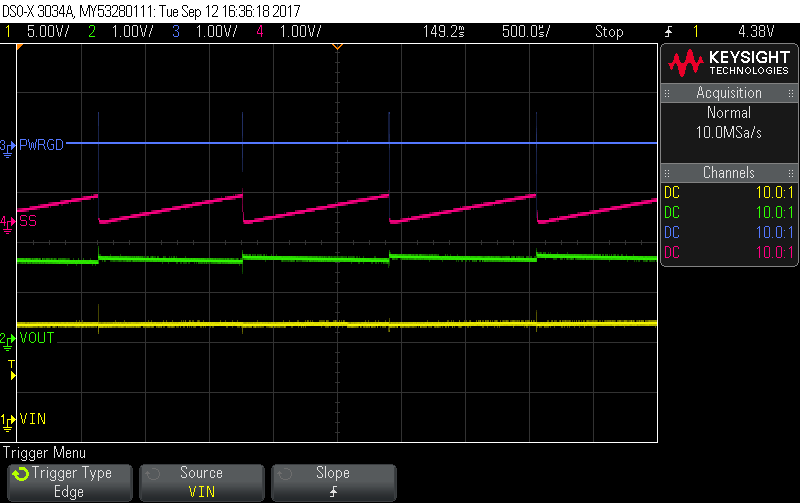
 

And zooming in:

Few comments:

1. AGND and PGND are connected together on the pcb (opposed to TI layout instructions which ask to separate it).).

2. INH gets an open drain output of a voltage monitoring device. The first pulse you see on this pin is a side effect of the same issue we see on a device which precedes this one (power sequencing wise).

3. The average load on the 1.8V is ~200mA (the board is still not fully active).

We think the issue is with the saw-tooth signal we see on the SS (slow-start) pin. We don't know the origin of it.


Any thoughts/ideas will be highly appreciated.

Thank you all,

Gil

  • Hello Gil,

    In deed, the saw tooth signal on the SS/TR pin looks weird. It look s like the device is powering up, then hits a limit, shuts down, soft start caps discharges, charges and then the device turns on again.

    There are some questions that could help solving your issue.

    a) What type of capacitors do you use? Can you provide part numbers?

    b) What kind of power supply do you use?

    c) Be sure that AGND pins 2 and 23 are connected external on your PCB.

    d) Is it possible to separate AGND from PGND on your board, like recommended by TI?

    e) The datasheet recommends at least one 47uF ceramic output capacitor. In your design there are four 22uF and four 2.2uF ceramic caps at the output. Try with at least one 47uF ceramic output cap.

    f) Your design has a total input capacitance (coming from ceramic caps) of 22.2uF. The minimal value recommended in the datasheet is 44uF. Try increasing the input capacitance. In general, place the input and output caps as close to the input and output pins as possible.

    Please don't hesitate to contact us again, in case you have more questions or discuss new results with your board.

    Michael
  • Hello Gil,

    My understanding is that this was resolved via email. Please let us know if you need additional help.

    Regards,
    Denislav
  • Hi Michael,

    We discovered that PH is shorted to VOUT and that caused this behavior.

    Removing the short fixed it.

    thanks

    Gil