This thread has been locked.

If you have a related question, please click the "Ask a related question" button in the top right corner. The newly created question will be automatically linked to this question.

LM3880: EN pin concern , I have voltage on EN when I power up the Vcc and nothing work

Part Number: LM3880

Hello

I am stuck since 3 weeks with a LM3880 sequencer basic circuit

1) I have purchased LM33880 from Farnell so that not grey source

2) I have FR4 PCB tested , solder mask

3) I use mask soldering and reflow with controlled temperature

4) I test short after soldering and make visual inspection

5) I have built two same test PCB I have same result on both

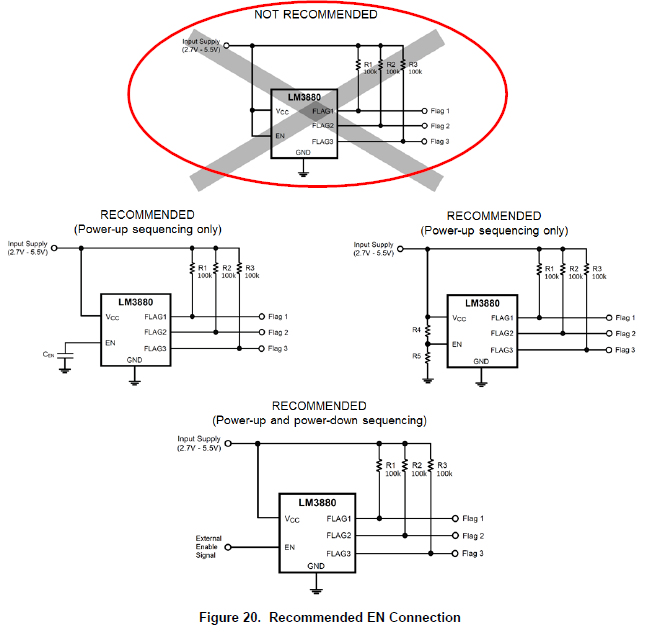
I want to test the LM3880 function after soldering but without output flag connected and with no ballast resistor assembly

A) When I power the LM3880 with 5 V on Vcc I can measure 4.70 V on the EN pin ( EN pin is open ) and I have no output on the flag

B) When I put 5 V DC by using a on / off switch on EN pin I have no output on the flag

Can you help by answering the following question :

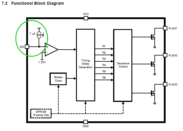
Question 1 does that normal to be able to have a voltage on EN pin when pin is open ( not connected ) that looks strange from my point of view

Question 2 shall I need to connect ballast before to make measurement on the flag output

Question 4 Does some one have already see defective LM3880

any other information will be great in the aim to solve this problem

Regards

David

  • Hi David,

    We will investigate and get back to you soon.

    Regards,
    Weidong
  • Hello Weidong

    Thanks , that LM3880 AB , I have ordered LM3880 AC and AF do test other batches I will post update

    on the TI doc there is no available values of EN voltage ( open pin ) but it sound logical that EN is an input so the Voltage shall be 0 V

    Regards

    David

  • Hi David,

    Did you order LM3880-EVM to try? or you can compare your own schematics with EVM(http://www.ti.com/lit/pdf/snva172) to see any obvious difference.

    The flag is a open drain, do you have a pull-up ?

    Regards

    Yihe

  • Hello , Yihe

    Thanks for your post

    regarding the demo board no I have copy and paste the concept

    right now I have no load on flag pin I will try this afternoon to set a load on flag

    The factory doc is very light regarding DO / DONT so that quite painful to play the apprentice sorcerer

    I test with load and post results

    Regards

    David

  • Hello

    I have other tests

    I have change the LM3880 ( same batch from Farnell ) for another I have the same result

    a) without load connected EN pin is at 4.50 V and nothing on the flag pin when I put EN 5V on EN pin

    b) with LED ( 25 ma ) connected on each flag ( + 100K ballast ) EN pin is at 4,5 V and nothing on the flag pin when i put 5 V on EN

    I try now another batch from Farnell , as Mouser parcel is still not delivered

    that understandable to lost so much time with a 6 pin chip so simple

    Regards

    David

  • hello

    I have on the SAME PCB :

    change the LM3880 by a LM3880 just received from Farnell ( hand soldered ) visual inspection checked

    with LED as load on 1 and 2 flag + 100 k ballast

    Pin EN I have 0.7 V ( open pin ) no output on flag

    Pin EN at 5 V no output on flag

    I have run several ON/OFF and get the same values

    the nightmare continue

    Regards

    David
  • Hello

    in the aim to progress I have some questions

    1) Does LM3880 is very sensitive chip ( ESD or other problem )
    2) Does LM3880 can be destroyed by power it up (Vcc to 5V ) without flag connected
    3) Does some component as LED are compatible just to load the flag or shall I use other ( to generate a 20 mA load as max is 50 mA )

    Regards

    David

  • Please refer the shematics (page 2) at www.ti.com/.../snva172a.pdf
    Regards
    Yihe
  • Hello

    I have make test with another PCB , ballast very close to the flag pins , reflow soldered

    LM3880 AC from Mouser new batch , previous one's was AB from Farnell

    Vcc 5V

    I have still 4.7 v on EN ( open pin )

    That incredible

    Regards

    David

  • Hello, Yine

    Thanks

    I have copy and paste the TI schematic
    I have soldered available LM3880 AB just to test as I am lost
    I have still 4.7 on EN ( open pin ) I have 4.7 V on all the LM3880 I can use
    and 2.70 V on Flag by using 10K and not 100 k resistor

    I have no control of EN

    that clearly not understandable

    Regards

    David

  • Why is it good to leave EN open? It is supposed to connect instead of floating.
    If you tie the EN to a ground or 3.3V to see whether the Flag will be low or high with 100K pull-up when VCC is normal.

    1) Does LM3880 is very sensitive chip ( ESD or other problem )
    No, LM3880 has passed specia ESD test described in the data sheet
    2) Does LM3880 can be destroyed by power it up (Vcc to 5V ) without flag connected
    No. it will not.
    3) Does some component as LED are compatible just to load the flag or shall I use other ( to generate a 20 mA load as max is 50 mA )
    It shall be fine.

    Regards

    Yihe
  • David,

    There is 4.7V on the open EN pin because there is a 7uA current source from VCC connected to the EN pin internal to the device.

    So if the EN pin is open it will follow the VCC pin. 

    And this is basically equivalent to having the EN pin tied to VCC at power-up which the datasheet does not recommend, see below.

    The EN pin should be exercised to active (High) after the device is powered up.

    For the last recommended case above, External Enable Signal, I would ensure that the EN pin is low before applying VCC otherwise you will be equivalent to the not recommended case again.

    Also, if you are seeing 2.7V on the FLAG pins with the EN pin High, then the FLAG pins are active but the voltage from the pull-up is being limited by something external to the sequencer,  I interpreted your post to indicate that the LEDs are tied from the FLAG pin to ground, this would be the likely source of voltage limitation.

    If the Enable was low then the FLAG pins should be <0.4V.

    The Pull-up resistance is probably too high to light the LEDs if you are using 10K or 100K resistors.

  •  Hello

    OK thanks your detailed answer

    so I cannot use the same 5 v PSU than the Vcc ?

    I link the pcb screen shot I use a manual toggle switch between EN and Vcc

    Shall I use another 5 V PSU ? as I have understood that I shall NOT drive EN and Vcc in the same time but that not written I shall use another PSU source ??????

    Regards

    David

  • David,

    You can use the same supply, but the switch connecting VCC to EN will need to be open at power up. And because the EN pin will be sourcing the 7uA, you will need to add a resistor from the EN pin to ground that will hold the pin below the minimum enable threshold of 1.0V during power up of the VCC rail. A 10K ohm on the EN pin to ground will hold the voltage to 0.07V when the switch is open.
  • thanks you are right That mandatory to NOT let EN pin floating but use a resistor ( 10K) that work now
    thanks