This thread has been locked.

If you have a related question, please click the "Ask a related question" button in the top right corner. The newly created question will be automatically linked to this question.

TPS25944L: protecting the LMR14030

Part Number: TPS25944L
Other Parts Discussed in Thread: LMR14030, , LM2596, TPS53353

I am trying to protect my LMR14030 DC/DC converter set to 3.3V and as well the 12V bus. The protection i made on the input side of the converter using TPS25944L.The idea is to protect also the 12V Bus where the converter is supplied from, also in case if the LM14030 gets an internal short/ LOW Side + High Side switch/ or whatever.

My assumption was so that I know the let say nominal steady state input current of the converter, so if it goes double to high in case of overload at the output or in case of internal shorts then TPS25944L will switch-off the circuit. I need a latch function.  Everything works fine if I am increasing the load at the output. I change the load (of the LMR14030) till the trigger point (my case 0.75A input of TPS25944 corresponding to 1.85A at 3.3V output).

Now is the problem. I have external reset-er which is periodically resetting the TPS25944  if there is a Fault flag.
So the problem occurs if there is a still to heavy load at the output and the  TPS25944 was commanded to start.

It is starting and if to heavy load still exist the whole circuit is oscillating and consuming power from the 12V bus. This must be avoided, if failure at the output it must try periodically to turn on the converter with the load, but after certain time 4ms must be off.

Circuit is oscillating for the load between the trigger point and the full metal short.

The question is how to keep the circuit off so long until there is an overload(over the trigger value) or short?
The TPS25944 is not switching off when its seeing short pulses, shorter than 4ms and integrator of those pulses would be very useful. It should try to turn on the LM14030, but as soon as it recognize overload conditions should goes off (after 4ms). There is somewhere a closed loop and its self oscillating.

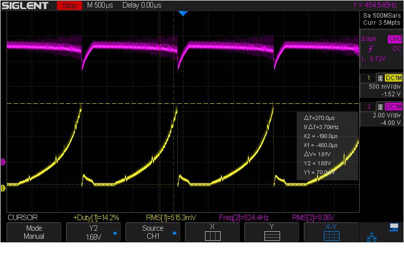
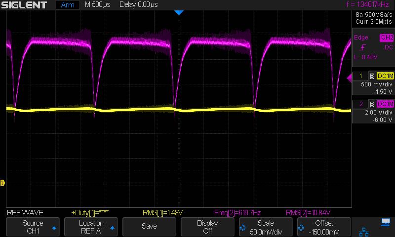
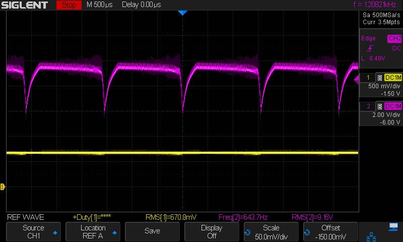
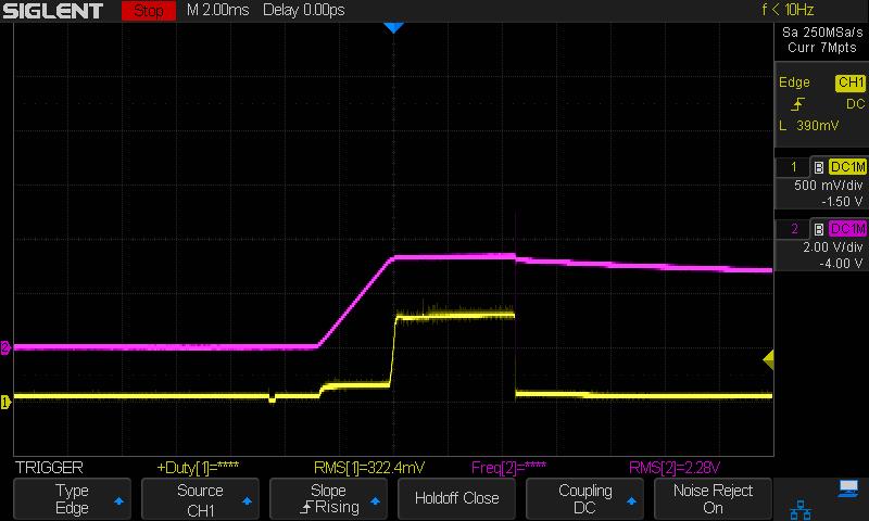
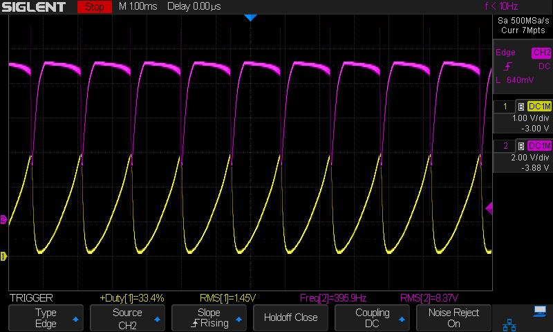
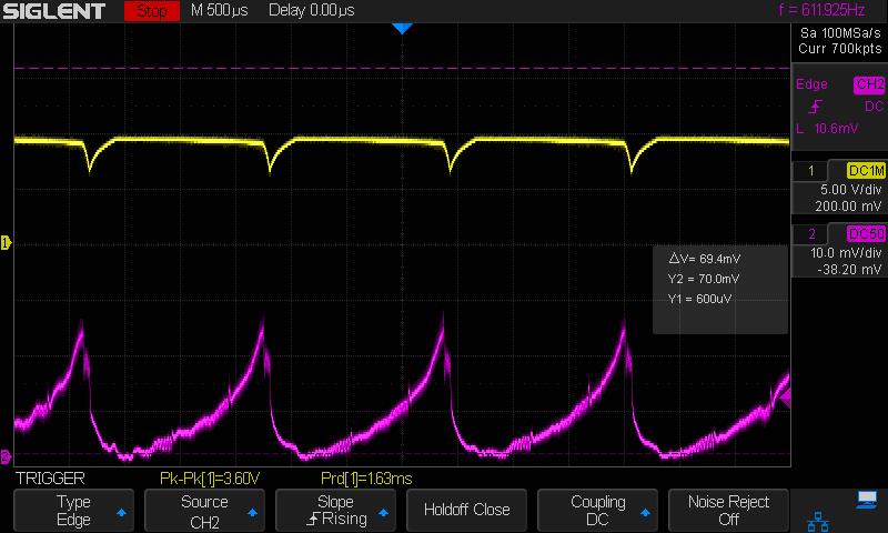
I enclose the picture the Pink is output Voltage from the TPS25944 ( Input was 9V from DC power supply limited to 1.25A average current from DC meter was about 0.4A).
Yellow is an Input current taken from Imon Pin (at  R 20k  to GND, its about 0,5A /0,5V). EN Pin of LMR14030 was pulled up to Vin to be sure its not a problem.

regards

  • Hi Christopher,
    Thanks for reaching out!.
    I will get back to you as soon as possible.

    Best Regards,
    Rakesh
  • Hi Christopher,

    Can you share me the schematic of TPS25944L and LMR14030 devices including input and output capacitance to look into it.
    Have you done any simulation? I guess this is a start up related and can be solved by connecting the PGTH output of TPS25944L to the enable pin of LMR14030 device OR increasing Css value of LMR14030.

    Best Regards,
    Rakesh
  • Hi Rakesh,

    Simulation- I do not have.


    This solution is not very appriciated. My idea is to use PGTH as protection against overvolatage at LMR14030 output.
    Currently the PGTH it is connected(wrongly) to the input of LMR. instead of its ouptut. I will check this way this might be a reason.
    My idea is so, If the 3.3 goes to hight let say to 3.5V this will switched off the TPS25944. So I will have overload and overvoltage protected 3.3 output, thats the wish.
    The LMR14030 has 22uF + 47nF inpuyt capacitance, it is placed between output off TPS and Input of LMR. I have increased even 220uF, but the problem was too. There is no input capacitance for the TPS it was straight to power supply ( at the moment).

    PGTH  is not a problem, actually it is used as a flag only, I wrongly tought it is restting the TPS.

    I enclose a picture,  of FLT PIN yellow, Pink is output of the TPS. This fault beahaviour :I think is due to the overshoot after switch off. When I add an extra 220uF to the input of TPS overshoot is disapearing, but circuit ist still oscilating after restart.

    Restart with 1R5 load at the output( almost short) Yellow 3.3 output Pink output from TPS

    Restart with 1 Ohm Load Yellow Vout 3.3 Pink out from TPS

  • What we can note from above is that the circuit is corectly switched off ( after restart which is needed) till the load of 1.5 Ohm, if there more low ohmic load circuit is starting oscilating. I guess this is all because of that that the TPS is not acumulating those pulses. It can be trigered either by the Itrip which in this case is to low or if the overcurrent is higher than the Ilim and longer than 4ms. Both cases are not true and...is oscilating.

    And all this strange behaviour is due to the LMR behaviour which is dynamic object.

    Rakesh:

    Let assume, I connect PGTH to the output of 3.3 converter (through the divider clear), and the Drain of PGD FET of TPS25944 to EN pin of the LMR14030 Pin ok. Now is such case:

    LMR is overloaded comparator in TPS will keep the LMR off, and somehow overload disapears, what will triger LMR to on state if TPS is keeping it off?

    I am afraid it will never start until you provide some voltage to the 3.3 output. Again. It is off, load removed , its still off becasue TPS is locking it  through EN. Or am I wrong?:

    Css capacitor in LMR was 10nF and 100nF, for 10n the output volateg is rising up in 2ms for 100n its about 20ms. 20 is to muchfor me,  there will be mcu at 3.3 output. But I tested it as well.

  • This is enable pin of LMR -yellow, pink is out from TPS- Treshold 1.2V +-50mV hyateresis seems ok

    And this is Enable Pin of TPS- falling treshold 0,92V - seems ok

    OVP Pin of TPS, rising treshold 0,99V -seems ok

  • Hi Christopher,

    Thanks for the test waveforms.
    Seems LMR part is restarting not the TPS part. The LMR14030 has cycle-by-cycle current limit protection for the high-side MOSFET. This may be shutting off and restarting the device. As discussed in yesterday's call, please monitor the currents for both the parts during this mode.

    Best Regards,
    Rakesh
  • I did a test with the LM2596 converter connected to the output of TPS25944.When I have a full short or partial short on the output set to 3.3V ( as in LMR) the TPS is correctly switched off after 4ms.
    Pink is output from TPS yellow is the current information from Imon pin(TPS). 0.5V/0.5A roughly

    I am still waiting for the current probe, however current information from the Imon pin seems correct, my limitation is set to 0.75A and it seems so during this 4ms period.
    What I do not like is that the LM2596 consumes about 6mA current in standby mode/no load. Therefore the LMR   was my choice as it is very good less than 1mA stdby current, what for my battery application is important.

    Now i need to find a way, if its possible, to connect the LMR and TPS correctly. I am afraid this is not possible because of the LMR behaviour, Do not you think so?

  • I still do not have current probe. Maybe it will arrive in next week.

    But i did another test with TPS56321evm board which has also this

    a cycle-by-cycle valley detect control circuit.
    this is result
    I think I need to use a converter without this cycle by cycle limit feature as it interact somehow with main e-fuse the TPS. What I need is a switcher like lm2596 but:
    with standby current around 1mA or less, and this would be very appreciate if such simple switcher would be easy paralleled with a second one.
    I have two sections for reliability reasons. If I couple them by the diodes in one output, current sharing ratio strongly depends on the output voltage and the drop on the diodes.
    Thermalpad is required and current output 2,3 Amps/ Internal switch.
  • Hi Christopher,

    I have reached out to LM2596 team to suggest a Switcher with Low operating quiescent current like LM2596 but without cycle-by-cycle current limit. The Engineer will get back to you shortly.

    Best Regards,
    Rakesh

  • Great. I tried to find something but if I am in a buck converters integrated switch group almost everything has cycle by cycle feature.
  • Hi Christopher,

    The feedback is .. Most of the switchers have integrated over-current protection.
    Have you tried by increasing the i/p capacitance of LMR14030 i.e., C41 value? Can you probe the output current of TPS device with a current probe to understand the overload condition.

    Best Regards,
    Rakesh
  • Yes I did C41 was 220uF, and even 2x220uF. However it was still oscillating with one C=220uF. Somehow it helps with 12V input, but if the input is 9V (battery low) it does not ( bigger input C needed in this case).
    And I can not increase this capacitance so easy, limit with space and some another critical requiments.

    I must repeat tests with current probe. I am still waiting for a current probe, its ordered and there are some customs declarations needed as it was imported from US. Takes time..

    As so far my current information was taken from the Imon output. I have a one idea how to avoid this. The TPS25944 would be a very good chip if ( it is partially)

    if it would integrate these currents spikes. Because if your system will try to start with short on the output it will jump in neverending loop.

    So my solution is so: i will take a signal from Imon pin and this will feed  through a diode (1N4148) to RC filter. ( simple peak sampling net) The voltage on the Capacitor should be equal to the current spike  amplitude, and this voltage will trigger some additional circuit which will pulls down the EN Pin, perhaps a delay is needed to not jump in another never-ending loop.

    I am trying to perform some simulation in PSpice , I am not sure if  TImodel is really so realistic. But i can verify this in hardware to its faster and more acqurate.

  • It has nothing to do with the main problem. But there is a Failure in datasheet,:

    SLVSCE9D–JUNE2014–REVISED OCTOBER 2017

    Point 9.4.2 the threshold is 0,99V and 0,92 for negative slope. Not 0.6 V ad in description above Figure 54. seems like type error.

  • Hi Christopher,

    Thanks for pointing out. we will correct it in the next datasheet revision.
    One suggestion on your circuit to try out! - Increase the soft-start time ( from present value --> 20ms-->100ms) of LMR and check whether it helps.

    Best Regards,
    Rakesh
  • But...The problem is that , from the LMR14030 uC is supplied and usually the rising time for uC should be less than 2ms.

    I have designed a circuit which based on the information from Imon pin is switching off the TPS25944. However I need several components for that, no place on board,

    and the other problem is that this puls down the EN pin, so without latch function it will jump in another never-ending loop. Long dealy is needed..

    The best solution would be if TPS would be latched off by itself, based on the Itrip current. Thus, LMR should sink high current spike, everything will be more clear with current probe which is still on the way..

  • Hi Christopher,

    As LMR14030 device has cycle-by-cycle current limit to protect against internal short/ LOW Side + High Side switch. Can you check whether TPS25944L device be used after LMR14030. i.e., at the output of LMR14030 device. I think, this way also the 12V bus gets protected against overload/short circuits.

    Best Regards
    Rakesh
  • If we are lucky. It must protect the battery and the common 12V battery bus, not the dc-dc converter. To protect the dc-dc converter cycle by cycle limiatation is good. But when it fails, system is dead, nobody will guarantee that. Thus, additional separated protection is needed on the input. If it fails redundant converter is useless.

    I have ordered additional EVM with TP65533 which should pulls much higher current  during short on its output, hopefully, this should trigger the TPS25944.

    Regarding to the increasing capacitor between TPS and LMR. If the capacitor is Big then during short on the output of LMR most of the energy/current during first cycles will come from this capacitor, and the current will flow not through TPS. Thus the big capacitance should be on the input of TPS to trigger it and latched of. Do not you think so Rakesh? I think so.

  • The input current of LMR measured with the current probe is similar to that one taken from the IMON pin, no big differences.
    0,5A/div pink, yellow  is12V Input voltage.

  • Summarizing this topic the TPS25944L is not able to protect the LMR14030 on the input side, this is due to the cycle by cycle current limitation feature. another dc dc controller were used TPS53353 which sucks much higher current

  • Hi Christopher,

    How much you compromised on the quiescent current with new dc-dc controller? What is the controller part no? - I am not able to find TPS63353.

    Best Regards,
    Rakesh
  • TPS53353 sorry for typo error. Iq is less then 1mA, its about 0,5mA.

    The peak current (during restart on the shorted output)  was in caseof the LMR14030  -5Amps and for the TPS53353 is 15A.