This thread has been locked.

If you have a related question, please click the "Ask a related question" button in the top right corner. The newly created question will be automatically linked to this question.

AM4379: Not work ethernet PHY

Part Number: AM4379
Other Parts Discussed in Thread: TMDSIDK437X

Hello.

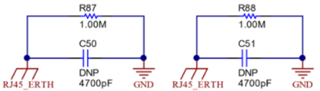
I created a circuit and a board of my device based on the TMDSIDK437x circuit. I do not start both Ethernet PHY of PRUs. Could you see my scheme, maybe there is something wrong?

MC_SOCADM437x_BaseModule_assembly.PDF

Regards, Dmitry.

  • Hello Dmitry,

    Please provide more information about your system and what you are observing.

    e.g., What version of the SDK are you using? Are you running RTOS or Linux on the ARM core? Do you see any meaningful output during boot time? etc.

    Regards,

    Nick

  • Hello.

    A little chronology. To study the system, I purchased a kit TMDSIDK437x. After studying, I took most of the schematic TMDSIDK437x for my project. If you require, I can provide the entire project outline. After I received the boards for my project, I started testing.

    To test the connection, I use a standard project from the SDK examples.

    SDK I use:    ti-processor-sdk-rtos-am437x-evm-06.03.00.106

    Example I use: NIMU_ICSS_BasicExample_idkAM437x_wSoCLib_armExampleproject

    Example works fine on board TMDSIDK437x. But on my board the device is not pinging. I haven't looked at any control signals yet. Tell me where to start. In general, the project is loaded via JTAG.

    I think I could make mistakes in connecting DP83822. Please pay attention to the connection scheme, is everything in it correct?

    Regards, Dmitry.

  • Hello Dmitry,

    I am going to send your thread to the PHY team to take a look from a connection side. Feel free to ping the thread if you do not receive a response in a day or so.

    Regards,

    Nick

  • Hi Dmitry,

    We're taking a look at your schematic and will get back to you by Wednesday.

    Thanks,

    Lucas

    All information in this correspondence and in any related correspondence is provided “as is” and “with all faults”, and it is subject to TI’s Important Notice (http://www.ti.com/corp/docs/legal/important-notice.shtml).

  • Hi Dmitry,

    Here is what we found after reviewing your schematic:

    • Since both VDDIO and AVD are connected to the same 3.3V source, it's possible that one supply could back-drive the other causing POR issues. Can you check the current draw and RX_CLK signal?
    • The decoupling capacitors on VDDIO and AVD seem low in value. You can refer to Figure 10-1 in the datasheet for our recommended decoupling caps.
    • PHY GND and shield GND should be isolated from each other. We recommend replacing C146 (and C171) with the following RC network:

    • Can you confirm that your crystal meets the datasheet spec?
    • On the INT/PWDN pin, we recommend a 2k pull-up resistor instead of a 10k PU.
    • What is the purpose of capacitors C132-C135 (and C157-C160)?
    • What is the purpose of resistors R89 and R94 (and R131 and R136)?
    • R80-R84 and C126-C127 (and R122-R126 and C151-C152) should be connected to AVD, not VDDIO.
    • C144 (and C169) should be 10nF, not 1nF.
    • Please note that both PHYs are strapped to the same PHY address so MDC/MDIO cannot talk to each PHY individually.

    Thanks,

    Lucas

    All information in this correspondence and in any related correspondence is provided “as is” and “with all faults”, and it is subject to TI’s Important Notice (http://www.ti.com/corp/docs/legal/important-notice.shtml).

  • Hello.

    Thanks for the answer. Capacitors C132-C135 (and C157-C160) is 4.7pF.

    You were right, I had the same PHY address. I removed the resistor R119, the scheme worked. Ethernet PRU0 is working. The program works and the exchange too. But Ethernet PRU1 I can't ping. I haven't figured it out yet, there may be problems with the program.

    There is only one question left. Maybe Ethernet PRU1 does not work because pin 29 (COL/GPIO2) of DR83822 is pulled up to 3.3V? Could it be better to use a different pin for PHY address configuration  MDC/MDIO?

    Regards, Dmitry.

  • Hi Dmitry,

    Is the COL pin of PRU1 currently pulled both up and down (via R151)? If this is the case then the PHY could be strapping to fiber mode which would cause the problem. If you remove the PD then PRU1 will keep a different PHY address without strapping fiber mode.

    Additionally we recommend following this table for strap resistor values. Please not that COL is internally PU and RX_D0-RX_D3 are PD.

    You can also double check registers 0x467 and 0x468 to confirm your strap settings.

    Thanks,

    Lucas

    All information in this correspondence and in any related correspondence is provided “as is” and “with all faults”, and it is subject to TI’s Important Notice (http://www.ti.com/corp/docs/legal/important-notice.shtml).

  • Hello.

    COL pin of PRU1 currently pulled only up, down (R151) is removed.

    I was able to check PRU1. PRU1 works and exchange too. How I did it. In the program code of stackInitHook I change Item value of new entry in CfgAddEntry. If Item value equal 1, then work PRU0. If Item value equal 2, then work PRU1.

    void stackInitHook(HANDLE hCfg)
    {
    CI_IPNET NA;
    CI_ROUTE RT;

    /* Add IP address for interface 1 */
    NA.IPAddr = inet_addr(ipAddr);
    NA.IPMask = inet_addr(ipMask);
    CfgAddEntry(hCfg, CFGTAG_IPNET, 2, 0, sizeof(CI_IPNET),(uint8_t *)&NA, 0 );

    /*
    * Add gateway for interface 1
    * --> I *think* the below should work but you may need different values ...
    */
    bzero(&RT, sizeof(RT));
    RT.IPDestAddr = 0;
    RT.IPDestMask = 0;
    RT.IPGateAddr = inet_addr(ipGateway);

    CfgAddEntry(hCfg, CFGTAG_ROUTE, 0, 0, sizeof(CI_ROUTE), (uint8_t *)&RT, 0);

    }

    Thus, we can conclude that the scheme as a whole works. 

    But a couple more questions arose.

    1. After starting the program, on both ports, when the network cable is connected, only one LED is lit, which is connected to pin 17 (LED_0). This is apparently related to the driver program setting. Tell me where to do it? Why isn't the other LED responding in any way?

    2. I could not figure out on my own how to make the program so that two ports could work at the same time. For the example, PRU0 had the address 192.168.1.5 and PRU1 had the address 192.168.1.7. Right now I can only work with one port. 

    Regards, Dmitry.

  • Hi Dmitry,

    1. Read register 0x462 bits[2:0]. If these bits have value 0 then the LED1 pin is tri stated. You can configure this pin to use an LED by writing 1 to these bits of register 0x462 or by changing the strap on the CRS pin (refer to section 8.5 of the datasheet). Once this pin is set up for an LED, you can use registers 0x460 and 0x469 to configure LED1.

    2. Can you read registers 0x0, 0x1, 0x10, and 0x11 on both PHYs when both ports are active? Can you also verify that the MAC interfaces don't change for this 2 port system? Just to let you know, I can only support you on ethernet issues, so if this ends up being a software issue I may need to reassign the thread.

    Thanks,

    Lucas

    All information in this correspondence and in any related correspondence is provided “as is” and “with all faults”, and it is subject to TI’s Important Notice (http://www.ti.com/corp/docs/legal/important-notice.shtml).

  • Hello.

    OK, my question regarding the circuitry is closed. Then I will create other topics on the program questions.

    Regards, Dmitry.