A related question is a question created from another question. When the related question is created, it will be automatically linked to the original question.
If you have a related question, please click the "Ask a related question" button in the top right corner. The newly created question will be automatically linked to this question.
There are a couple known issues that could be causing this:
There is a known issue with the out-of-box experience that prevents it from loading from within TI Resource Explorer - to workaround this you will need to open the out-of-box experience in a new tab or window. This will be fixed within the following week.
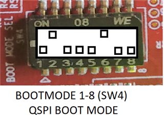
We've received reports that some of the LaunchPads from the first batch do not have the SOC initialization binary pre-flashed which causes the out-of-box experience to fail. You can check if your LaunchPad is one of these by connecting the LP to your PC and opening a UART terminal. Make sure your LP is set to QSPI Boot Mode. When powering on the board you should see the following output on your UART terminal if your LaunchPad is pre-flashed. If you don't see this then you will need to flash your LP as described here: https://software-dl.ti.com/mcu-plus-sdk/esd/AM243X/latest/exports/docs/api_guide_am243x/EVM_SETUP_PAGE.html#EVM_FLASH_SOC_INIT
  Starting NULL Bootloader ...

  DMSC Firmware Version 21.1.1--v2021.01a (Terrific Lla
  DMSC Firmware revision 0x15
  DMSC ABI revision 3.1

  INFO: Bootloader_runCpu:147: CPU r5f1-0  is initialized to 800000000 Hz !!!
  INFO: Bootloader_runCpu:147: CPU r5f1-1 is initialized to 800000000 Hz !!!
  INFO: Bootloader_runCpu:147: CPU m4f0-0 is initialized to 400000000 Hz !!!
  INFO: Bootloader_loadSelfCpu:199: CPU r5f0-0 is initialized to 800000000 Hz !!!
  INFO: Bootloader_loadSelfCpu:199: CPU r5f0-1 is initialized to 800000000 Hz !!!
  INFO: Bootloader_runSelfCpu:209: All done, reseting self ...
Also, please make sure you have selected the correct serial port for the out-of-box experience, "XDS110 Class Application/User UART"
Please let us know if you are still unable to connect after trying the steps above.
Can you confirm your LaunchPad is in QSPI boot mode as shown below?
You should see the following output on the UART terminal, confirming the SOC has been properly initialized and is running.
  Starting NULL Bootloader ...

  DMSC Firmware Version 21.1.1--v2021.01a (Terrific Lla
  DMSC Firmware revision 0x15
  DMSC ABI revision 3.1

  INFO: Bootloader_runCpu:147: CPU r5f1-0  is initialized to 800000000 Hz !!!
  INFO: Bootloader_runCpu:147: CPU r5f1-1 is initialized to 800000000 Hz !!!
  INFO: Bootloader_runCpu:147: CPU m4f0-0 is initialized to 400000000 Hz !!!
  INFO: Bootloader_loadSelfCpu:199: CPU r5f0-0 is initialized to 800000000 Hz !!!
  INFO: Bootloader_loadSelfCpu:199: CPU r5f0-1 is initialized to 800000000 Hz !!!
  INFO: Bootloader_runSelfCpu:209: All done, reseting self ...
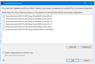
At this point you can connect to the R5s and load programs via CCS.
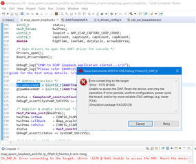
We've recently discovered an issue which requires connecting the micro-USB JTAG cable after powering on the LaunchPad. Can you please try this if you haven't already and let us know if it helps?
I tried as you suggested, power up board by USB Type C first, then connect the Micro USB, still no CCCCCCC printing out in UART booting mode, i also try to reset the chip by SW1/SW2/SW3, no improvement so far.