


Other Parts Discussed in Thread: AM5749
Hello.
I have a TMDSIDK574 AM5749 board and would like to know about the DDR3 setup.
EMIF_RegisterConfig.xlsm (www.ti.com/.../sprac36)
was used to compare with the TMDSIDK574 set value.
EMIF_RegisterConfig
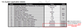
AM57x, DRA7x, and TDA2x Corrected items 13 and 14 according to the EMIF Tools guide.
The u-boot source used is the latest version of ti-processor-sdk-linux-am57xx-evm-06.03.00.106.
1. the values in the Register values (U-Boot) tab are different from the u-boot source contents. I want to know the reason.
ti-processor-sdk-linux-am57xx-evm-06.03.00.106/board-support/u-boot-2019.01+gitAUTOINC+333c3e72d3-g333c3e72d3/arch/arm/mach-omap2/omap5/hw_data.c
const struct ctrl_ioregs ioregs_dra7xx_es1 = {
.ctrl_ddrch = 0x40404040,
.ctrl_lpddr2ch = 0x40404040,
.ctrl_ddr3ch = 0x80808080,
.ctrl_ddrio_0 = 0x00094A40,
.ctrl_ddrio_1 = 0x04A52000,
.ctrl_ddrio_2 = 0x84210000,
.ctrl_emif_sdram_config_ext = 0x0001C1A7,
.ctrl_emif_sdram_config_ext_final = 0x0001C1A7,
.ctrl_ddr_ctrl_ext_0 = 0xA2000000,
};
ti-processor-sdk-linux-am57xx-evm-06.03.00.106/board-support/u-boot-2019.01+gitAUTOINC+333c3e72d3-g333c3e72d3/board/ti/am57xx/board.c
static const struct dmm_lisa_map_regs am574x_idk_lisa_regs = {
.dmm_lisa_map_2 = 0xc0600200,
.dmm_lisa_map_3 = 0x80600100,
.is_ma_present = 0x1
};
static const struct emif_regs am574x_emif1_ddr3_666mhz_emif_ecc_regs = {
.sdram_config_init = 0x61863332,
.sdram_config = 0x61863332,
.sdram_config2 = 0x08000000,
.ref_ctrl = 0x0000514d,
.ref_ctrl_final = 0x0000144a,
.sdram_tim1 = 0xd333887c,
.sdram_tim2 = 0x30b37fe3,
.sdram_tim3 = 0x409f8ad8,
.read_idle_ctrl = 0x00050000,
.zq_config = 0x5007190b,
.temp_alert_config = 0x00000000,
.emif_ddr_phy_ctlr_1_init = 0x0024400f,
.emif_ddr_phy_ctlr_1 = 0x0e24400f,
.emif_ddr_ext_phy_ctrl_1 = 0x10040100,
.emif_ddr_ext_phy_ctrl_2 = 0x00910091,
.emif_ddr_ext_phy_ctrl_3 = 0x00950095,
.emif_ddr_ext_phy_ctrl_4 = 0x009b009b,
.emif_ddr_ext_phy_ctrl_5 = 0x009e009e,
.emif_rd_wr_lvl_rmp_win = 0x00000000,
.emif_rd_wr_lvl_rmp_ctl = 0x80000000,
.emif_rd_wr_lvl_ctl = 0x00000000,
.emif_rd_wr_exec_thresh = 0x00000305,
.emif_ecc_ctrl_reg = 0xD0000001,
.emif_ecc_address_range_1 = 0x3FFF0000,
.emif_ecc_address_range_2 = 0x00000000
};
Among the output of EMIF Tool Register values (u-boot)
const unsigned int AM574x_DDR3L_666MHz_TI_AM574x_IDK_emif1_ext_phy_regs[] = {
0x04040100, /* EMIF1_EXT_PHY_CTRL_1 */
0x006B00C0, /* EMIF1_EXT_PHY_CTRL_2 */
0x006B00BC, /* EMIF1_EXT_PHY_CTRL_3 */
0x006B00C7, /* EMIF1_EXT_PHY_CTRL_4 */
0x006B00C3, /* EMIF1_EXT_PHY_CTRL_5 */
0x006B00D1, /* EMIF1_EXT_PHY_CTRL_6 */
0x002F002F, /* EMIF1_EXT_PHY_CTRL_7 */
0x002F002F, /* EMIF1_EXT_PHY_CTRL_8 */
const unsigned int AM574x_DDR3L_666MHz_TI_AM574x_IDK_emif2_ext_phy_regs[] = {
0x04040100, /* EMIF2_EXT_PHY_CTRL_1 */
0x006B00BC, /* EMIF2_EXT_PHY_CTRL_2 */
0x006B00BB, /* EMIF2_EXT_PHY_CTRL_3 */
0x006B00C7, /* EMIF2_EXT_PHY_CTRL_4 */
0x006B00C4, /* EMIF2_EXT_PHY_CTRL_5 */
0x006B006B, /* EMIF2_EXT_PHY_CTRL_6 */
0x002F002F, /* EMIF2_EXT_PHY_CTRL_7 */
0x002F002F, /* EMIF2_EXT_PHY_CTRL_8 */
Where should the output refer to?
ti-processor-sdk-linux-am57xx-evm-06.03.00.106/board-support/u-boot-2019.01+gitAUTOINC+333c3e72d3-g333c3e72d3/arch/arm/mach-omap2/omap5/sdram.c
should you refer to?
2. Please provide a detailed description of the field data.
Reference schematic
AM574x Industrial Development Kit (IDK) Schematic — SPRR351.ZIP
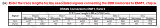
2A) Signal CLK field stripline value is the schematic pin (Proj PROC053 001 OPN# TMDSIDK574)
Byte 0 : AM5749ABZXEA DDR1_CK - U5 DDR_CLK
ECC : U7 DDR_CLK - U6 DDR_CLK
Is the connection correct? What pins are byte1 ~ byte3 connected to? Please provide a detailed explanation.
2A) Signal DQSn field stripline value is the schematic pin (Proj PROC053 001 OPN# TMDSIDK574)
Byte 0 : AM5749ABZXEA DDR1_DQS0n - U5 DDR_DQSn0
ECC : AM5749ABZXEA DDRECC_DQSn- U6 DDRECC_DQSn
Is the connection correct? What pins are byte1 ~ byte3 connected to? Please provide a detailed explanation.
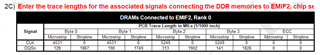
2C) The EMIF2 field cannot be fully filled with pin connection. Please explain in detail which value is correct.
Please help me to understand.
