This thread has been locked.

If you have a related question, please click the "Ask a related question" button in the top right corner. The newly created question will be automatically linked to this question.

OMAP-L138: OMAP-L138 SPI0 SPIBUF not updating

Part Number: OMAP-L138

Hi,

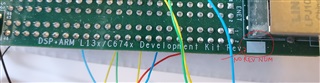
I am trying to use OMAP-L138/C6748 development kit SPI0 (on ARM core) to communicate with external device (connected on J15 of OMAP L138 dev board).

The OMAP is setup to use 4pin master mode (with CS4 used for SPI0), sending out SPI data at bit rate of 1Mb/s and the slave device responds with expected byte,

I originally used the example loop-back code and modified it to communicate with external device.

but SPIBUF register in OMAP is not updating as per the response I see on SOMI line, the value of this register in debug register view is 0 and reading the register returns 0x00.

Setup:

- I am using TI-RTOS and its example code as startup guide and modified it.

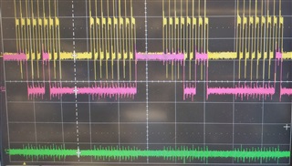
- I can confirm SPI_CLK, SIMO and SOMI states by checking these signals on oscilloscope. please check the waveform image (yellow trace is SPI_CLK and pink one is response back from slave device on SOMI).


- I have updated the PINMUX3 as per SPI0 4Pin mode requirements. I have attached code snippet here, after this code execution the PINMUX3 value = 0x88141181.

-------------------------------------------------------------------------------------------------------

    hSysCfg->PINMUX3 &= (~(
           // CSL_SYSCFG_PINMUX3_PINMUX3_31_28_MASK | not used
           // CSL_SYSCFG_PINMUX3_PINMUX3_27_24_MASK | not used
           CSL_SYSCFG_PINMUX3_PINMUX3_23_20_MASK | // SPI0 used 
           CSL_SYSCFG_PINMUX3_PINMUX3_19_16_MASK | // GPIO used for Enable
           CSL_SYSCFG_PINMUX3_PINMUX3_15_12_MASK | // SPI0 used
           CSL_SYSCFG_PINMUX3_PINMUX3_11_8_MASK  | // SPI0 used 0
           // CSL_SYSCFG_PINMUX3_PINMUX3_7_4_MASK |   not used
           CSL_SYSCFG_PINMUX3_PINMUX3_3_0_MASK)    // SPI0 used
    );

    hSysCfg->PINMUX3  |= ((CSL_SYSCFG_PINMUX3_PINMUX3_23_20_SPI0_SCS4 << CSL_SYSCFG_PINMUX3_PINMUX3_23_20_SHIFT) |
                          (CSL_SYSCFG_PINMUX3_PINMUX3_19_16_GPIO8_4 << CSL_SYSCFG_PINMUX3_PINMUX3_19_16_SHIFT)   |
                          (CSL_SYSCFG_PINMUX3_PINMUX3_15_12_SPI0_SIMO << CSL_SYSCFG_PINMUX3_PINMUX3_15_12_SHIFT) |
                          (CSL_SYSCFG_PINMUX3_PINMUX3_11_8_SPI0_SOMI << CSL_SYSCFG_PINMUX3_PINMUX3_11_8_SHIFT)   |
                          CSL_SYSCFG_PINMUX3_PINMUX3_3_0_SPI0_CLK
    );

-------------------------------------------------------------------------------------------------------


- SPIPC0 register fields reflects the setting that I wish to work with, i.e. SPI pin functions for CLK, SIMO, SOMI and SCSFUN[4] are true.

SPIPC0 = 0x01010E10


- R214, R215, R216 were not populated on dev kit, I installed these resistors as well, so SPI0 pins are connected to J15 of the board (where we have connected the slave device and also tapping the signals for oscilloscope).

- also confirmed R275 (pull up) is available on LCDK board.


Can somebody please help me identify what could be the problem that I am not receiving the data available at SOMI pin in my SPIBUF register?


Thanks,

  • Looking at OMAP-L138 Technical Reference Manual, Section 30.2.18 "Emulation Consideration".

    It mentions that SPIBUF should not be read by debugger, I am using XDS100v3 debugger and CCS v10.3.1. Should I use some settings to disable reading this register during debug?

    if so how can I do that? I did not find any such mention in section 7 of this doc <https://software-dl.ti.com/ccs/esd/documents/users_guide/index_debug.html>

  • Hi,
    I have a couple questions just to help me understand the issue that you're facing.

    Which exact version of the development kit are you using?

    And since you mentioned that you modified the example loopback code, did you make any changes besides the PINMUX3 changes that you showed earlier? If so, could you include some additional code snippets of the changes that you made?

    Since you're connecting to an external device, have you tried starting with one of the other non-loopback SPI examples instead? 

    Best regards,
    Dillon

  • Hi Dillon,

    > I tested external physical loop-back between MOSI and MISO, it works on another omap L138 board that I have but not on the original one. Also I tried SPI1 on original board here input/output both worked fine but SCS3 was not working (even in GPIO mode SCS3 pin was not doing anything). is it possible that on original board some of the pins are internally damaged?

    > the dev kit rev is not mentioned on PCBs, it is blank white space.

    > Other than pinmux, I am using modifies initialization for SPI0.

    void SPI0_Initialize(uint32_t spi_cs, SPI_FrameFormat frame_format, uint32_t clock_frequency_in_hz, uint32_t data_size_in_bits, SPI_TransferMode transfer_mode, SPI_Mode mode, uint32_t timeout_mode)
    {
        SPI_Params      spiParams; /* SPI params structure */
        SPI_v0_HWAttrs spi_cfg;

        /* Get the default SPI init configurations */
        SPI_socGetInitCfg(SPI_INSTANCE_0, &spi_cfg);

        spi_cfg.enableIntr = false;
        spi_cfg.csNum = SPI_CS(spi_cs);

        SPI_socSetInitCfg(SPI_INSTANCE_0, &spi_cfg);

        /* Open the Board flash NOR device with the test SPI port
           and use the default SPI configurations */
        SPI_Params_init(&spiParams);

        spiParams.frameFormat = frame_format;
        spiParams.bitRate = clock_frequency_in_hz;
        spiParams.dataSize = data_size_in_bits;  // TODO: Check that 8 bits works with Wifi module
        spiParams.transferMode = transfer_mode;
        spiParams.mode = mode;
        spiParams.transferTimeout = timeout_mode;

        // to keep CSHOLD Disabled
        //((SPI_v0_Object*)hwHandle->object)->transferComplete //SPI0_terminate_transfer_dummy;

        /* Init SPI driver */
        SPI_init();

        hwHandle = (SPI_Handle)SPI_open(SPI_PORT_0, &spiParams);
    }

    in above method passed in parameter values are:

    SPI0_Initialize(4, SPI_POL0_PHA1, 1000000, 8, SPI_MODE_BLOCKING, SPI_MASTER, SPI_WAIT_FOREVER);

    > data transfer functions are used as given in TI-RTOS examples with added logic surrounding it (for sanity check)

        SPI_control(hwHandle, SPI_V0_CMD_XFER_ACTIVATE, (void *)&xferEnable);

        if(SPI_transfer(hwHandle, &transfer) == false)

    > the loopback example came in a package that I downloaded from TI website, in this package there were no other SPI related examples (only loop back examples for ARM and DSP and with and without DMA). could you please guide me from where can I get more example codes for OMAP-L138?

    Thanks,

  • If one board is working, but the other is not, it's likely that the boards are just different revisions from one another.

    Apologies about that, I should've been more clear with my question. I'm mostly looking for which exact version of the software development kit that you have.

    Besides the "transferComplete" line, which looks a little interesting in regards to the issue you're facing, everything else looks generally good.

    Since the code that I've seen looks generally good, my next suggestion would be to connect your board to the CCS debugger, and set break points or step through the code during the transactions. And while doing so, record or take screenshots of the SPI values that you see. From there, we may be able to see if you're missing something in particular.

    For OMAP-L138 you can download the latest software development kit from here: https://www.ti.com/tool/PROCESSOR-SDK-OMAPL138

    Best regards,

    Dillon

  • Hi Dillon,

    Thanks for reply,

    board:

    I still dont know how to get the board revision, as I said the REV is not marked on either of the board I have.

    we are assuming the processor pins could be damaged is that possibility? (we are observing same behavior on other pin as well on this particular board e.g. SPI1 SCS3 pin is not working, meaning can not control this as chip_select while working with SPI1 and have it configured to use as SPI function,  showing similar behavior SPI0SOMI).

    debug:

    I have been debugging this using XDS100v3 debugger and CCS v10.3.1. I have checked the SPIBUF register values during and after transfer, the value always remains 0x00 (even when I pull up the SOMI). other flag registers for SPI0 updates normally as if it has read the data correctly, and spi drivers (from example code) does not return any error condition.

    ignore:

    the "transferComplete" line is commented out in this code,

    I wanted to know range of values I can use to assign to object->transaction->arg to toggle chip select but I am updating CSHOLD after each transfer to control chip select (I have mentioned this in another post on this forum).

    e2e.ti.com/.../3840045

    Thanks,

  • Damaged pins could be a possibility. Could you also try swapping the power supplies of the two boards and trying again? Also, did you receive these boards during our early release? Or did you receive them recently?

    And what values do you see for RXBUF before, during, and after transfers?

    Best regards,

    Dillon

  • power supply does not seems to be an issue. as I mentioned other pins of the SPI0 (for example SPI MOSI and SPI_CLK) are working fine.

    we purchased this board during mid this year.

    in non-working board RXBUF always reads 0x00 before and after the transfer, though as I mentioned rx flags gets updated.

    Experiment1:

    we wrote simple code to test spi physical loop-back (connect MOSI and MISO physical line externally via a resistor). without changing the code(and configuration), without changing powersupply or Jtag debugger, we just swap the boards, in first board we do not see SPIBUF getting any values back (always reads 0x00) in another board we see SPIBUF gets the value that we sent out on MOSI pin.

    after this experiment we concluded the board's MISO pin is damaged.

    Experiment2:

    Using this damaged board's dmaged SPI MISO pin as GPIO input just worked fine.

  • Earlier in this post you mentioned that you modified R214, R215, R216, and J15. Did you make the same modifications to the working board?

    Also, just to make sure I'm understanding properly, when using the working board, is everything regarding SPI working? Or does it still show some issues?

    Best regards,

    Dillon

  • Regarding R214 to R216: Yes we installed those on both boards.

    On working board SPI related all pins functions as expected, we are able to communicate with external SPI device.

  • In that case, there may be something faulty with your first board. Let me check with my colleague about the process for damaged boards.

    Best regards,

    Dillon

  • Hi Kuldeep,

    Since the board was modified and you soldered a few resistors onto it, we are unfortunately unable to tell if the issue originated from the original board, or from the resistor modifications that were made. More than likely, you will have to purchase a new board since there have been user modifications to it. But, if you'd like to try to see if the board could be swapped for a new one, follow the steps at the following "Customer returns" link below:

    https://www.ti.com/support-quality/additional-information/customer-returns.html

    Hope this helps.

    Best regards,

    Dillon