

Other Parts Discussed in Thread: DRA829,
A custom board will need to do some software tweaks on top of TI SDK. Is there a board bring up guide that
gives reference examples of changes that need to be done.

This thread has been locked.
If you have a related question, please click the "Ask a related question" button in the top right corner. The newly created question will be automatically linked to this question.
The Jacinto 7 EVMs are a reference development platform with a superset of peripherals to showcase the SoC's capability. The customer develops a board based on their own use cases that need to be supported on their platform. Therefore, there is typically a cut down on peripherals, change in the peripheral parts chosen, and changes in the number of instances of supported peripherals. This eventually leads to a different design, and the pinmux and power requirements change. A list of such common changes & how to adapt SDK to incorporate the changes are described below:
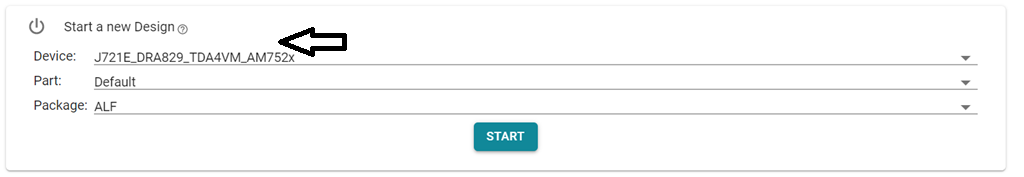
The recommended way of configuring the PinMux for Jacinto devices is by using the PinMux tool. This tool is available online as well as installer is available & can be used offline.
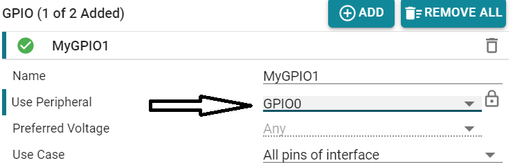
Steps to configure the PinMux:
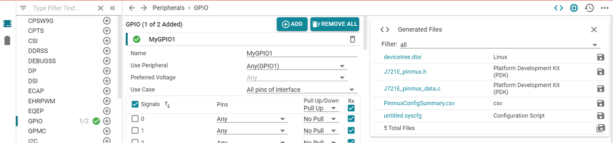

/* This file was auto-generated by TI PinMux on 7/22/2020 at 9:21:31 AM. */
/* This file should only be used as a reference. Some pins/peripherals, */
/* depending on your use case, may need additional configuration. */
&main_pmx0 {
mygpio1_pins_default: mygpio1_pins_default {
pinctrl-single,pins = <
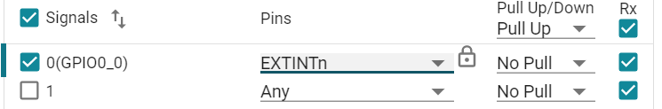
J721E_IOPAD(0x0, PIN_INPUT, 7) /* (AC18) EXTINTn.GPIO0_0 */
>;
};
};The same can be followed with u-boot device tree. The very same example arch/arm/dts/j721-common-proc-board.dts file
Manual audit of the pinmux:

Custom boards can have different PMICs sourcing the SoC voltage domains. Choosing different
PMIC can be due to cost benefits, different power requirements & availability. The PMIC configuration
is typically done in the safety safety aware MCU R5F0. R5 SPL primarily configures the CPU rail with
AVS compensated voltages. Changes will be needed for custom PMIC in 2 places:
1) Device Tree: The device tree for WKUP_I2C0 needs to be populated with the right PMIC nodes. Example: arch/arm/dts/k3-j721e-r5-common-proc-board.dts
Hook the right regulator node as the supply for VTM node.
&wkup_i2c0 {
        u-boot,dm-spl;
        tps659413a: tps659413a@48 {
                reg = <0x48>;
                compatible = "ti,tps659413";
                u-boot,dm-spl;
                pinctrl-names = "default";
                pinctrl-0 = <&wkup_i2c0_pins_default>;
                clock-frequency = <400000>;

                regulators: regulators {
                        u-boot,dm-spl;
                        buck12_reg: buck12 {
                                /*VDD_MPU*/
                                regulator-name = "buck12";
                                regulator-min-microvolt = <800000>;
                                regulator-max-microvolt = <1250000>;
                                regulator-always-on;
                                regulator-boot-on;
                                u-boot,dm-spl;
                        };
                };
        };

&wkup_vtm0 {
        vdd-supply-2 = <&buck12_reg>;
        u-boot,dm-spl;
};
2) CONFIG changes for PMIC in configs/j721e_evm_r5_defconfig for example below are the changes needed for TPS65941 PMIC:CONFIG_DM_PMIC=y
CONFIG_PMIC_TPS65941=y
CONFIG_DM_REGULATOR=y
CONFIG_SPL_DM_REGULATOR=y
CONFIG_DM_REGULATOR_TPS65941=y
Custom boards can have different DDR parts. Choosing different
DDR parts can be due to cost benefits, different memory requirements & power design. All the
DDR related configuration & initialization happens in R5 SPL. We will need to generate a
custom DT file to address differences. We need to replace: arch/arm/dts/k3-j721e-ddr-evm-lp4-4266.dtsi
with a custom dts file corresponding to the chosen DDR part. This involves using the DDR config tool.
The details are captured in the below application note.
https://www.ti.com/lit/pdf/spracu8
The first & primary goal is to bring up Linux on the custom board with TDA4. It is always better & easier to start
with minimal device tree that covers just the boot media, console UART, Timers & other necessary DT nodes.
The following zip file contains patches disabling the peripheral nodes that are NOT essential for booting Linux.
The default device tree provided in the SDK is a super set of all the peripheral support for TDA4. Hence optimization
in DT is needed to avoid crashes/hangs due to a peripheral mismatch in custom board. Choose the minimal set
of nodes & boot to Linux prompt with that. Post that customer can enable the nodes relevant for their custom board.
Here is a set of reference DT optimization patches for Linux on 8.0 SDK:
0001-arm64-dts-j721e-Enable-Minimal-DT-configuration.patch
Here is a set of reference DT optimization patches for Linux on 7.3 SDK:
8512.boot-time-opt-7.3.zip
To be added
1. Custom dts files in U-Boot:
The U-Boot framework expects a k3-j721e-common-proc-board-u-boot.dtsi for A72 SPL
corresponding to k3-j721e-common-proc-board.dtsi.
So if a customer board has DTS file named k3-j721e-custom-board.dts then one should
add k3-j721e-custom-board-u-boot.dts. That is mandatory for A72 SPL.
2. MMC UHS typically causes hang at A72 SPL stage. Disabling that as below:
The j7 boot flow is explained here: https://git.ti.com/gitweb?p=ti-u-boot/ti-u-boot.git;a=blob_plain;f=board/ti/j721e/README;hb=HEAD
R5 SPL does not support UHS hence issues related to UHS do not occur at the R5 SPL stage.
The error is because the A72 SPL supports UHS for SD cards. UHS stands for Ultra high speed.
The UHS feature needs a switch of vqmmc supply voltage from 3.3V to 1.8V. In case the regulators
are not populated the switch fails and hence the A72 SPL hangs at that stage.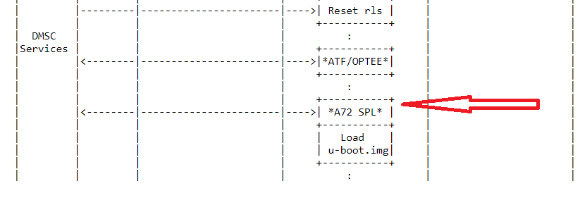
So we can disable the UHS feature to quickly get to u-boot prompt. By following steps:
step 1: Make the following changes in the u-boot defconfig:
diff --git a/configs/j721e_evm_a72_defconfig b/configs/j721e_evm_a72_defconfig
index fa3d5bc439..a1d5040af8 100644
--- a/configs/j721e_evm_a72_defconfig
+++ b/configs/j721e_evm_a72_defconfig
@@ -110,10 +110,10 @@ CONFIG_K3_SEC_PROXY=y
CONFIG_MISC=y
CONFIG_DM_MMC=y
CONFIG_SUPPORT_EMMC_BOOT=y
-CONFIG_MMC_IO_VOLTAGE=y
-CONFIG_SPL_MMC_IO_VOLTAGE=y
-CONFIG_MMC_UHS_SUPPORT=y
-CONFIG_SPL_MMC_UHS_SUPPORT=y
+#CONFIG_MMC_IO_VOLTAGE is not set
+#CONFIG_SPL_MMC_IO_VOLTAGE is not set
+#CONFIG_MMC_UHS_SUPPORT is not set
+#CONFIG_SPL_MMC_UHS_SUPPORT is not set
CONFIG_MMC_HS400_SUPPORT=y
CONFIG_SPL_MMC_HS400_SUPPORT=y
CONFIG_MMC_SDHCI=y
Step 2: Make the following changes in u-boot device tree:
diff --git a/arch/arm/dts/k3-j721e-common-proc-board.dts b/arch/arm/dts/k3-j721e-common-proc-board.dts
index 15b33309a5..15594d728e 100644
--- a/arch/arm/dts/k3-j721e-common-proc-board.dts
+++ b/arch/arm/dts/k3-j721e-common-proc-board.dts
@@ -162,8 +162,8 @@
        pinctrl-names = "default";
        pinctrl-0 = <&main_mmc1_pins_default>;
        ti,driver-strength-ohm = <50>;
-       vmmc-supply = <&vdd_mmc1>;
-       vqmmc-supply = <&vdd_sd_dv_alt>;
+       no-1-8-v;
+       sdhci-caps-mask = <0x8000000F 0x0>;
 };
step 3: make u-boot
Step 4: copy the tispl.bin u-boot.img to the boot partition of your SD card.
This should avoid UHS feature from hanging and get us to u-boot prompt.
3. Switching the console to different UART. Example how to switch console to MCU_UART from MAIN_UART
As per the boot flow we have 3 stages.
So we need to change at all levels. On top of that ATF(Arm Trusted Firmware) also needs to change the console port as needed.
Following are the dts changes on J7200 & similar changes for J721e will work fine:
diff --git a/arch/arm/dts/k3-j7200-common-proc-board-u-boot.dtsi b/arch/arm/dts/k3-j7200-common-proc-board-u-boot.dtsi
index f55c71f0c4..5d641f3074 100644
--- a/arch/arm/dts/k3-j7200-common-proc-board-u-boot.dtsi
+++ b/arch/arm/dts/k3-j7200-common-proc-board-u-boot.dtsi
@@ -5,7 +5,7 @@

/ {
chosen {
- stdout-path = "serial2:115200n8";
+ stdout-path = "serial1:115200n8";
tick-timer = &timer1;
};

diff --git a/arch/arm/dts/k3-j7200-common-proc-board.dts b/arch/arm/dts/k3-j7200-common-proc-board.dts
index 4a4600cd87..23fbfb95dc 100644
--- a/arch/arm/dts/k3-j7200-common-proc-board.dts
+++ b/arch/arm/dts/k3-j7200-common-proc-board.dts
@@ -11,7 +11,7 @@

/ {
chosen {
- stdout-path = "serial2:115200n8";
+ stdout-path = "serial1:115200n8";
bootargs = "console=ttyS2,115200n8 earlycon=ns16550a,mmio32,0x02800000";
};
'
The above dts changes take care of the SPL/u-boot side.
Now we also need to change in ATF (Arm Trusted Firmware).
Attached patch needs to be applied on top of ATF directory in the SDK:
From 54990cac252c3f2eadfd5027198501817f2e5af0 Mon Sep 17 00:00:00 2001
From: Keerthy <j-keerthy@ti.com>
Date: Tue, 23 Mar 2021 21:56:29 +0530
Subject: [PATCH] plat: ti: k3: include: platform_def.h: Change console UART
 from MAIN_UART0 to MCU_UART0

Change console UART from MAIN_UART0 to MCU_UART0.

Signed-off-by: Keerthy <j-keerthy@ti.com>
---
 plat/ti/k3/include/platform_def.h | 4 ++--
 1 file changed, 2 insertions(+), 2 deletions(-)

diff --git a/plat/ti/k3/include/platform_def.h b/plat/ti/k3/include/platform_def.h
index 690c68e5c..db083ca2f 100644
--- a/plat/ti/k3/include/platform_def.h
+++ b/plat/ti/k3/include/platform_def.h
@@ -91,14 +91,14 @@

 /* Platform default console definitions */
 #ifndef K3_USART_BASE
-#define K3_USART_BASE 0x02800000
+#define K3_USART_BASE 0x40a00000
 #endif

 /* USART has a default size for address space */
 #define K3_USART_SIZE 0x1000

 #ifndef K3_USART_CLK_SPEED
-#define K3_USART_CLK_SPEED 48000000
+#define K3_USART_CLK_SPEED 96000000
 #endif

 /* Crash console defaults */
--
2.17.1
Follow the below instructions to apply and compile:
cd $SDK_PATH/board-support/trusted-firmware-a-2.3
git am 0001-plat-ti-k3-include-platform_def.h-Change-console-UAR.patch.txt
make CROSS_COMPILE=aarch64-linux-gnu- ARCH=aarch64 PLAT=k3 TARGET_BOARD=generic SPD=opteed
cp ./build/k3/generic/release/bl31.bin ../prebuilt-images/
cd ../..
make u-boot
cp board-support/u-boot_build/A72/tispl.bin board-support/u-boot_build/A72/u-boot.img /media/$USER/BOOT
In case you want to avoid compilation of ATF: Just unzip & use the attached binary:
6320.bl31.zip
copy it directly to $SDK_PATH/prebuilt-images
then 'make u-boot' to make the new bl31.bin part of tispl.bin.
