This thread has been locked.

If you have a related question, please click the "Ask a related question" button in the top right corner. The newly created question will be automatically linked to this question.

TMS320C6748: [FAQ] How do I create a CCS project for TI-RTOS (SYS/BIOS) development on C674x DSP using the Processor SDK?

Part Number: TMS320C6748
Other Parts Discussed in Thread: OMAP-L138, OMAPL138

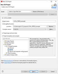
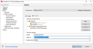
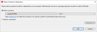
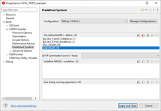
I'm going to start TI-RTOS development on C674x DSP using the Processor SDK RTOS. How can I get started?

  • The PDK component in the Processor SDK contains example CCS projects. Please refer to this FAQ on how to create example CCS projects from PDK, or refer to this FAQ for CCS ProjectSpecs.

    Here we describe how to create a CCS project from scratch. We’ll first use the CCS project wizard to create a SYS/BIOS template project and then add PDK components from Processor SDK RTOS 6.3 (PDK 1.0.17) for OMAP-L138/C6748. The complete project including the prebuilt executable is attached here as a reference: C674x_TIRTOS_example.zip

    1. Go to CCS -> File -> New -> Project -> Code Composer Studio -> CCS Project, click Next.

    2. Fill in the necessary fields for the new project:

    3. Click Next and choose products for this project:

    • Click SYS/BIOS and choose 6.76.3.01 which was used by pdk_omapl138_1_0_11.
    • In the XDCtools settings, put any text for Platform for now. Then click Finish

    4. The project should be created now. Go to project properties -> General -> Products. Choose the platform corresponding to your EVM from the Platform drop down list. This example uses the OMAP-L138 LCDK as the EVM and we choose ti.platforms.evmOMAPL138. Then click Apply and Close.

    5. Build the project by right clicking the project and then clicking “Build Project”. From the build process, you’ll notice that SYS/BIOS is built from source for C674x DSP. After the build finishes, the project’s output executable is located in the Debug folder and has .out extension.

    6. Follow this link to setup the OMAP-L138 LCDK.  Launch the LCDK and connect ARM9_0 and then connect C674X_0.

    7. Load the .out file to the OMAP-L138 LCDK. Step through the code and observe the execution. The code should enter Bios_start(), execute task taskFxn() and then go to idle. The System_printf messages should be displayed in CCS CIO console.

    8. Now let's add PDK components to the project. First we need to add OMAP-L138 PDK (assuming it’s already installed to CCS). Go to project properties -> General -> Products and click Add… Choose omapl138pdk 1.0.11.

    9. Then we need to add PDK components to the RTSC/XDC configuration file app.cfg. The necessary components for this example are: osal, csl, board, gpio, uart, and i2c. Please note that i2c is not directly used in this example but required by board. Below is the code for csl and gpio as an example:

    var devType = "omapl138"
    
    /*use CSL package*/
    var Csl = xdc.loadPackage('ti.csl');
    Csl.Settings.deviceType = devType;
    
    /* Load the gpio package */
    var Gpio = xdc.loadPackage('ti.drv.gpio');
    Gpio.Settings.enableProfiling = false;    
    Gpio.Settings.socType = devType;
    

    Also add SYS/BIOS Event Combiner which is needed by osal:

    var ECM = xdc.useModule('ti.sysbios.family.c64p.EventCombiner');


    Please refer to app.cfg of the project zip file for details.

    10. Modify main.c by adding Board_init, GPIO_init, GPIO_toggle, and UART_printf. Please refer to main.c in the project zip for details.

    11. Add GPIO configuration for OMAP-L138 LCDK. We’ll just use an example configuration from the PDK and add source code pdk_omapl138_1_0_11\packages\ti\drv\gpio\test\led_blink\omapl138\GPIO_board.c to the project.

    12. Add compiler symbols which are needed by GPIO configuration. Go to Project Properties > Build > C6000 Compiler > Predefined Symbols. Add SOC_OMAPL138 and lcdkOMAPL138.

    13. Build the project. Load .out to OMAP-L138 LCDK and run it. LED D5 on the board should blink and the UART_printf messages should be displayed in UART console.