This thread has been locked.

If you have a related question, please click the "Ask a related question" button in the top right corner. The newly created question will be automatically linked to this question.

AM3356: TPS65910 VDDx_REG - UBOOT configuration

Guru 15510 points
Part Number: AM3356
Other Parts Discussed in Thread: TPS65910,

Hi,

I have questions about AM335x Linux u-boot and configuration of TPS65910 VDDx_REG bit[5](ILMAX).

In u-boot source code(board.c) of TI AM335x Linux SDK, there are configurations of TPS65910 via I2C.
But there are no configuration of TPS65910 VDDx_REG register bit[5](ILMAX).

Does user need to add code which setup the TPS65910 VDDx_REG register value [ILMAX] in the u-boot usually or not?

When [ILMAX] is set to '0', the maximum load current of TPS65910 VDDx will be 1.0[A],
and when set to 1, the maximum load current of VDD2 will be 1.5[A].

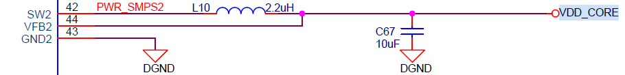
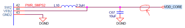
If VDD2(TPS65910) are connected to VDD_CORE(AM3356) which maximum current is 400mA,
should I add the code of setting the  ILMAX to 0(max 1.0[A]) to the u-boot?

best regards,
g.f.

  • Hi,

    according to the TPS65910 datasheet (Functional Registers section) the default ILMAX setting for all the different regulators is 0 so you don't need to explicitly configure it to zero.

    Regards, Andreas

  • Hi Andreas,

    Thank you for the reply.

    I understood that we don't need to set ILMAX to zero in u-bbot.
    But let me ask a few more questions.

    Q1. If using TPS65910 with AM3356 and the case that ILMAX need to be set to '1'(1.5[A]),
    should the ILMAX set to '1' in the u-boot?

    Q2. If yes, where in u-boot it should be set and chould you tell me the sample code to set the ILMAX?

    best regards,
    g.f.

  • g.f.,

    Q1: if you want to set ILMAX to '1', yes that should be done in U-Boot as part of all the other low-level board-specific setup.

    Q2: The easiest would be to extend the existing U-Boot driver at drivers/power/pmic/pmic_tps65910.c to add a function that allows controlling the ILMAX setting. This driver already has a local function called tps65910_write_reg() you can use to easily make additional register writes. Then, call your newly-added function from your board-specific init file (such as board/ti/am335x/board.c) right after the TPS65910 is initialized and configured for I2C mode. Basically add your extra init call to configure ILMAX _after_ the tps65910_set_i2c_control() call, which itself is made after the initial call to power_tps65910_init().

    Regards, Andreas

  • Hi Andreas,,

    Thank you for the reply.
    And I'm so sorry for the delay.

    My customer are having issue on their customer board, and I'm posting at the following post:
    e2e.ti.com/.../4199227

    The issue is that AM3356 VDD_CORE current goes 0mA->600mA->0mA->600mA at the timing of VDD_CORE voltage are supplied.
    And this phenomenon are happening at customer board and also at AM335x Starter Kit.
    On AM335x Starter Kit, VDD_Core will be about 0mA->400mA->0mA->400mA.
    On the starter kit, after powering the board on by pressing SW5, VDD_CORE goes up to 1.1[V] and
    the load current will repeat 0mA -> 400mA -> 0mA -> 400mA for a while(maybe during u-boot).

    At the above E2E, I got some advise that changing ILMAX(current limit) of TPS65910A31 value from 1.0A to 1.5A
    might improve the ripple of current.
    The issue arrives when the VDD_CORE rise up, so I think setting in the u-boot is not the right place.
    But I don't know when I should set the ILMAX.
    (I was told to throw a question to the Linux(u-boot) thread, so I posted here)

    When should I set the ILMAX?
    Is it the initialization part of u-boot?

    best regards,
    g.f.

  • Hi g.f.,

    would you be able to send a scope shot (current trace) showing the VDD_Core current event you are describing during startup on the TI AM335x Starter Kit (and let us know which exact TI SDK you are running on)? With this we'll be able to get some advise from the hardware team if that is expected or not.

    Regards, Andreas

  • Hi Andreas,

    Thank you for the reply.

    I attached the waveform of RESET, VDD_CORE volatage and current.

    1207.AM335x StarterKit_VDD_CORE_near_CPU.pptx

    I'm sorry I don't know which version of TI SDK they are using, but from the log they provided to us
    it seem that u-boot and kernel version is as following:
    Image Name : Arago/3.2.0-psp04.06.00.08.sdk/a
    Linux Kernel version is v3.2.0

    best regards,
    g.f.

  • g.f.,

    thank you for the scope shot. I've provided it to our hardware team for review to see whether this is expected behavior or not and will report back here.

    Image Name : Arago/3.2.0-psp04.06.00.08.sdk/a
    Linux Kernel version is v3.2.0

    This seems quite old but thanks for confirming the version. Will keep this in mind as we investigate this further.

    Also just to clarify something. Do you see any issues with the board not starting up? I wonder what motivated this investigation in the first place.

    Regards, Andreas

  • Hi Andreas,

    Thank you for the reply and I'm sorry for the delay.

    On 20 to 30 out of 100 manufactured customer boards, uboot starts up, but stops in the middle and restarts repeatedly.
    But on AM335xx StarterKit, u-boot starts and never stop.

    As I said at the above thread, on the customer boards, AM3356 VDD_CORE current goes 0mA->600mA->0mA->600mA
    at the timing of VDD_CORE voltage are supplied.

    My customer is thinking that this problem might be occured because of the current repeat 0mA->600mA->0mA->600mA.
    And they want to know what causes the current to be 0mA repeatedly.

    This current phenomenon are happening at customer board and also at AM335x Starter Kit.
    On AM335x Starter Kit, VDD_Core will be about 0mA->400mA->0mA->400mA.
    On the starter kit, after powering the board on by pressing SW5, VDD_CORE goes up to 1.1[V] and
    the load current will repeat 0mA -> 400mA -> 0mA -> 400mA for a while(maybe during u-boot).

    At other E2E forum, I was told that changing ILMAX register bit of TPS65910A31 might improve this issue.
    If this change will improve the issue(0mA->400mA->0mA->400mA) on the AM335x StarterKit,
    the customer will try it on the customer board in the next step.
    But we don't know when we should change the ILMAX, should it be changed in u-boot or elswhere?
    That is why I'm asking the configuration timing of ILMAX in this thread.

    Ultimately, the customer want to know why 0mA->600mA->0mA repeats and why it goes down to 0mA.

    best regards,
    g.f.

  • g.f.,

    thanks for the additional info. I'm asking our HW team to review your info in detail. If we need changes to SW I can then pick this back up and guide that (yes it'd need to be changed in U-Boot as it does the initial PMIC setup, and we'd need to do PMIC setting changes as early as possible).

    Regards, Andreas

  • Hi Andreas,

    Thank you for asking to your HW team.
    Do you have any updates from the HW team yet?

    best regards,
    g.f.

  • Hi g.f.,

    our HW team looked at the waveform and I got feedback that it looks normal and is nothing to be concerned about. Also no concerns running AM335x from that were raised.

    Regards, Andreas

  • Hi Andreas,

    Thank you for the reply.

    Our customer thought that repeating 0mA is the problem.
    And they want to know why it repeats 0mA.
    Do you mean that repeating 0mA->600mA->0mA->600mA(VDD_CORE current) is normal?
    But on customer board as I posted above, u-boot will stop at the middle of process and the boot will repeat(kernel never goes up).

    best regards,
    g.f.

  • g.f,

    there was no concern from a current change point of view according to the HW team. Perhaps there is some other reason why U-Boot sometimes stop. Let me spend some time tomorrow to re-review all the related threads and see if anything spikes out.

    Regards, Andreas

  • Hi Andreas,

    Thank you so much for supporting me.
    I will wait for the updates from you.

    best regards,
    g.f.

  • I have not gotten a chance to look at this again due to other high-priority work items but I'll try to do so tomorrow (Tuesday) and report back. Thanks for your patience.

  • Hi g.f.,

    I had a chance to re-review the thread, and the related thread here: https://e2e.ti.com/support/processors-group/processors/f/processors-forum/1125357/am3356-vdd_core-load-current-is-abnormal/4199227#4199227

    As for the current switching that's being discussed...

    As I said at the above thread, on the customer boards, AM3356 VDD_CORE current goes 0mA->600mA->0mA->600mA
    at the timing of VDD_CORE voltage are supplied.

    My customer is thinking that this problem might be occured because of the current repeat 0mA->600mA->0mA->600mA.
    And they want to know what causes the current to be 0mA repeatedly.

    ...it seems those currents were measured in a way that they capture the current across the inductor of the switched-mode power supply (SMPS) circuit. That is not really a valid way to capture the the VDD_CORE current as you are capturing the operation of the SMPS itself as it regulates and tries keeping the voltage at the capacitor constant by way of modulating the charging of the inductor, so it is expected for this current to fluctuate (actually it should fluctuate across some baseline value and NOT go to zero --> there may be some issue how you are measuring this current). This is usually only of interest when you want to observe the switching operation itself to perhaps fine tune inductor/capacitor values and SMPS operating settings for maximum efficiency or minimum ripple for example. In the other thread Sreenivasa already concluded that the VDD_CORE output voltage itself meets processor specifications (something I also confirmed with the HW apps team independently) and this is really what the primary careabout should be when it comes to determine whether this would relate to your failed boots.

    I think we need to take a step back and look at the boot failures from a different angle. First let me ask some more clarifying questions. Some of this may have gotten discussed somewhere already but I'd like to re-summarize with the latest understanding.

    1. Can you share the complete boot log from when the boot is failing?
    2. How does it fail? Just stops booting?
    3. When it does fail, does it it always fail at the same place (U-Boot UART print)?
    4. How repeatable are those failures on a given board?
    5. Are the failures limited to a specific set of boards? I believe somewhere else in one of the threads it was said 20% of boards are affected

    Then, one more experiment to do. On a failing board, can you remove the connection from the PMIC to VDD_CORE, and instead source that voltage rail from an external DC power supply? You would want to make sure the keep the device in PWRONRST until you have turned on VDD_CORE which itself should happen after you powered on the board and had the PMIC power up all the other rails to observe the device's power-up sequence (see device datasheet). This way we can eliminate the PMIC from the equation and see what this does.

    Regards, Andreas

  • Hi Andreas,

    Thank you for the reply and I'm very sorry for the delay.

    I got the boot logs and the answer of your question from my customer, so let me share at here.

    >Can you share the complete boot log from when the boot is failing?
    The board that causes the problem always reboots in the middle of u-boot.
    To be precise, basically it will start rebooting when operation move from u-boot to Linux "Starting Kernel....".
    But there are two patterns for the timing of rebooting, which depends on the board.
    One pattern is after "Starting kernel ..." displayed, and in another pattern, "Arago Project" is displayed,
    and after a while it becomes Kernel Panic and it starts reboot.
    My customer have captured the log of the boot when it fails and I attached the following log file to this post,
    so please take a look at it.
    1.boot_failure_log_starting_kernel.pdf

    boot_failure_log_starting_kernel.pdf
    2.boot_failure_log_reboot_after_Arago_project.pdf

    boot_failure_log_reboot_after_Arago_project.pdf

    >How does it fail? Just stops booting?
    As I mentioned at above, it reboots in the middle of u-boot.

    >When it does fail, does it it always fail at the same place (U-Boot UART print)?
    As mentioned above, there are two patterns for the timing of reboot, and it depends to the board.
    Basically, reboot occurs after "Starting Kernel..." in the attached "boot_failure_log_starting_kernel.pdf".
    However, some boards reboot after the "Arago Project"in the attached "boot_failure_log_reboot_after_Arago_project.pdf",
    so not all boards reboot at the same place.

    >How repeatable are those failures on a given board?
    It happens every time on the board which the problem occurs.

    >Are the failures limited to a specific set of boards? I believe somewhere else in one of the threads
    >it was said 20% of boards are affected
    If they manufacture 100 boards, the failure will occur in about 20 to 30 boards.

    best regards,
    g.f.

  • Hi Andreas,

    That is not really a valid way to capture the the VDD_CORE current as you are capturing the operation of the SMPS itself as it regulates and tries keeping the voltage at the capacitor constant by way of modulating the charging of the inductor, so it is expected for this current to fluctuate (actually it should fluctuate across some baseline value and NOT go to zero --> there may be some issue how you are measuring this current).

    Could you also point us where is the correct place to measure VDD_CORE current?
    For example in below schematics, VDD_CORE current should be measured at SoC side after C67?

    Thanks and regards,
    Koichiro Tashiro

  • Could you also point us where is the correct place to measure VDD_CORE current?
    For example in below schematics, VDD_CORE current should be measured at SoC side after C67?

    Yes, correct. The current needs to be measured on the SoC side of C67.

    I got the boot logs and the answer of your question from my customer, so let me share at here.

    Thank you for all the detailed information. From the logs and failure signature it seems that the system actually boots reasonably welI. I think it could also be a DDR-related issue and I think this is something we should investigate. Generally speaking the further you go down the boot process the more DDR is being exercised, making catastrophic system failures more likely in case there is some setup or board issue. Can you share some details of your DDR setup (devices used, setup parameters, etc.)? Then, ideally we would run 'memtester' to perform memory stress testing but I guess we won't be able to do that on the failing board. Perhaps doing this on the "good" boards may provide some insight as well if there is perhaps some marginal behavior. Once you share some details about the DDR setup I'll run this by our DDR expert.

    Then, one more experiment to do. On a failing board, can you remove the connection from the PMIC to VDD_CORE, and instead source that voltage rail from an external DC power supply? You would want to make sure the keep the device in PWRONRST until you have turned on VDD_CORE which itself should happen after you powered on the board and had the PMIC power up all the other rails to observe the device's power-up sequence (see device datasheet). This way we can eliminate the PMIC from the equation and see what this does.

    Is it possible for you to run this experiment?

    Regards, Andreas

  • Hi Andreas,

    Thank you for the reply and I'm sorry for the delay again.

    As you requested, we are now asking the customer to share their DDR3 parameters, so please wait for a while.
    And they tryied memory test by using "memtester" on their good board, but the version of
    TI Linux((Linux version 4.14.67) they're using doesn't seem to support the "memtester".
    Could you please tell me the detailed steps to make "memtester"support in this version of linux ?

    >On a failing board, can you remove the connection from the PMIC to VDD_CORE, and instead source that voltage
    >rail from an external DC power supply?

    The customer already tried this experiment and the result was successful.
    They supplied 1.2V externally to VDD_CORE of the failing board and the board have booted successfully.
    The customer gaved us the detailed report but I shouldn't attach the report to this forum,
    but TI local FAE Tashiro-san will send the report to you by email, so could you please check the report.

    best regards,
    g.f.

  • The customer already tried this experiment and the result was successful.
    They supplied 1.2V externally to VDD_CORE of the failing board and the board have booted successfully.

    Oh this is great to hear they ran this experiment already, I think that really pins the problem to the power supply then. I suggest we stop investigating the memory setup for now and re-focus back on power supply concerns.

    What I would suggest as a next step is to provide schematic and PCB layout offline to TI via Tashiro-san so we can have our HW team do a detailed review.

    Regards, Andreas

  • Hi Andreas,

    Thank you for the reply.

    I understood to re-focus back on power supply concerns.
    I requested the schematic and PCB layout to my customer, so please wait for a while.

    By the way, we understood to re-focus back on power supply, but could you also tell us the detailed steps to make "memtester" support in TI Linux version 4.14.67 for future use case? Because my customer are requesting the detailed steps.

    best regards,
    g.f.

  • I requested the schematic and PCB layout to my customer, so please wait for a while.

    We received the files and I provided them to our HW team for a detailed review, thanks. Will update the result hopefully next week.

    By the way, we understood to re-focus back on power supply, but could you also tell us the detailed steps to make "memtester" support in TI Linux version 4.14.67 for future use case? Because my customer are requesting the detailed steps.

    I don't know about the old SDK the customer is using but 'memtester' is part of our current SDK default images already (below example is from AM62x EVM).

    root@am62xx-evm:~# memtester
    memtester version 4.3.0 (64-bit)
    Copyright (C) 2001-2012 Charles Cazabon.
    Licensed under the GNU General Public License version 2 (only).
    
    pagesize is 4096
    pagesizemask is 0xfffffffffffff000
    need memory argument, in MB
    
    Usage: memtester [-p physaddrbase [-d device]] <mem>[B|K|M|G] [loops]
    root@am62xx-evm:~# 
    

    It is a pretty standard utility and provided through the Bitbake recipe located at `./meta-openembedded/meta-oe/recipes-benchmark/memtester/memtester_4.3.0.bb` in our current distribution. And it gets pulled into the image through the ./meta-arago/meta-arago-distro/recipes-core/packagegroups/packagegroup-arago-bootstrap.bb package group. You should be able to replicate this with whatever old Yocto distribution you use. The utility probably also has little to no external dependencies so you could just directly cross-compile it as well.

    Regards, Andreas

  • Hi Andreas,

    Thank you for the reply.
    We will wait for the review results.

    And thank you for explaining the memtester.
    I will tell the customer to cross compile and try it first.

    best regards,
    g.f.

  • Hi all,

      I'm the current Apps for the PMIC device; I'm waiting for the schematic and PCB layout to review all details. 

    Thanks!

    Phil