This thread has been locked.

If you have a related question, please click the "Ask a related question" button in the top right corner. The newly created question will be automatically linked to this question.

[FAQ] TDA4VM: PDK Interrupt registration for R5F using OSAL

Part Number: TDA4VM

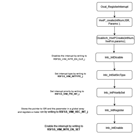
This document is intended to explain the interrupt registration process for R5F cores used in TI PDK

  • There are two steps for configuring the interrupts, interrupt routing and registration of interrupt with the core. TI PDK uses sci client calls to route the interrupts to the core and used OSAL layer to register the core interrupts and hook the required ISR with the interrupt. This document explains the registration process. This document explains how OSAL registration works for R5F with the explanation of register set involved.

    Register Set Description

    For R5F cores, vectored interrupt manager, (VIM), aggregates the device interrupts and send them to R5F cores. VIM supports 512 interrupt inputs per R5F core. Whenever an interrupt input goes high, if the interrupt is enabled, it will cause an IRQ to assert. This section explains some of the important VIM registers which can be useful when it comes to debugging R5F interrupt issues.

    R5FSS_VIM_RAW_j  (0-F)

    This is the RAW status register for group M. All the 512 interrupts are divided into 16 groups, with 32 interrupts per group. Each bit of the R5FSS_VIM_RAW_j  register represents the corresponding interrupt for that group. For example: core interrupt 33 will be represented by 1st bit of the R5FSS_VIM_RAW_2 register. If this bit is set, it means that core interrupt 33 is active or pending. This is a good indicator to know that your interrupts are routed properly.

    R5FSS_VIM_STS_j (0-F)

    This register indicates the masked status of interrupt of the group. Any bit reading 1 indicates that the corresponding interrupt is enabled and bit reading 0 indicates that the interrupt is masked/disabled. This register can be read to make sure that the required interrupt is enabled.

    R5FSS_VIM_INTR_EN_SET_j (0-F)

    Used to enable the interrupts in a group. Writing 1 to any bit enables the corresponding interrupt for a given group. Make sure that the interrupt is enabled to trigger an IRQ.


    R5FSS_VIM_INTR_EN_CLR_j (0-F)

    Used to disable the interrupts in a group. Writing 1 to any bit disables the corresponding interrupt for a given group.

    R5FSS_VIM_INTTYPE_j (0-F)

    Used to indicate the type of interrupt, level or pulse for a given group.  0 means a level interrupt, 1 means it is a pulse

    R5FSS_VIM_PRI_INT_j (0-1FF)

    Use to set the priority of interrupt. Each of the register (0-1FF) contains the sets the priority for corresponding interrupt. Priority can be 0-Fh, with 0 being the highest priority.


    R5FSS_VIM_VEC_INT_j (0-1FF)

    Used to store the address of the corresponding ISR.


    R5FSS_VIM_ACTIRQ

    Stores the information about active IRQ. Bit 0-9 of this register can be checked to know the current active IRQ number. This is a good indication to check that your interrupt register configurations are correct.

    Flow of interrupt registration :