


Other Parts Discussed in Thread: AM5728, PCM5310
Hi TI Audio Champs
We'd like to ask you about McASP config when the system clock is connected to PCM codec without AM5718.
Based on AM5728 evm, Customer trying to implement mcasp part with AM5718 (playback function)
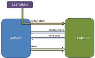
Referring to AM5728 below, they confirmed that it works normally in conjunction with PCM5310 as shown below.
(22.5792 was received as XI_OSC1 same as AM5728 evm and linked to mclk of PCM5310 with clkout2.
The audio sample plate is 44100 Hz.)
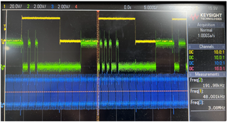
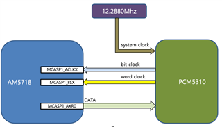
But similarly, if the system clock passes without going through AM5718 as shown below, sync is not correct.
And even if the interface clock is changed, the data rate is not changed.
The data is not even output according to the word clock.
(yellow: work clock, green: data(arx0), blue:interface clock)
Questions :
We wonder how to create a device tree in AM5718 to implement as follows.
Or, if you need to modify the code, please advise me which part I should modify.
They wrote the device tree as below.
sound0: sound0 {
...
sound0_master: simple-audio-card,codec {
sound-dai = <&pcm5310>;
clocks = <&ex_clkin>;
};
};
ex_clkin: ex_clkin {
#clock-cells = <0>;
compatible = "fixed-clock";
clock-frequency = <12288>;
clock-output-names = "ex_osc";
};
..
&mcasp1 {
#sound-dai-cells = <0>;
assigned-clocks = <&ipu_clkctrl DRA7_MCASP1_CLKCTRL 24>;
assigned-clock-parents = <&ex_clkin>;
status = "okay";
We attached the device tree file and the mcasp1 setting.
/*
 * Copyright (C) 2015-2016 Texas Instruments Incorporated - http://www.ti.com/
 *
 * This program is free software; you can redistribute it and/or modify
 * it under the terms of the GNU General Public License version 2 as
 * published by the Free Software Foundation.
 */
#include "dra72x.dtsi"
//#include "dra74x.dtsi"
#include <dt-bindings/gpio/gpio.h>
#include <dt-bindings/interrupt-controller/irq.h>
#include "dra7-mmc-iodelay.dtsi"

// #include "dra72x-mmc-iodelay.dtsi"
#include "dra74x-mmc-iodelay.dtsi"

#include "dra7-ipu-dsp-common.dtsi"
//  #include "dra74-ipu-dsp-common.dtsi"

#include "am57xx-industrial-grade.dtsi"

/ {
	compatible = "ti,am5718-idk", "ti,am5718", "ti,dra7";

	aliases {
		// rtc0 = &tps659038_rtc;
		rtc0 = &rv3029_rtc;
		rtc1 = &rtc;
		display0 = &hdmi0;

		sound0 = &sound0;
		sound1 = &hdmi;
	};

	chosen {
		stdout-path = &uart3;
	};

	memory@80000000 {
		device_type = "memory";
		reg = <0x0 0x80000000 0x0 0x40000000>;
	};

	reserved-memory {
		#address-cells = <2>;
		#size-cells = <2>;
		ranges;

		ipu2_memory_region: ipu2-memory@95800000 {
			compatible = "shared-dma-pool";
			reg = <0x0 0x95800000 0x0 0x3800000>;
			reusable;
			status = "okay";
		};

		dsp1_memory_region: dsp1-memory@99000000 {
			compatible = "shared-dma-pool";
			reg = <0x0 0x99000000 0x0 0x4000000>;
			reusable;
			status = "okay";
		};

		ipu1_memory_region: ipu1-memory@9d000000 {
			compatible = "shared-dma-pool";
			reg = <0x0 0x9d000000 0x0 0x2000000>;
			reusable;
			status = "okay";
		};
	};

	vmain: fixedregulator-vmain {
		compatible = "regulator-fixed";
		regulator-name = "VMAIN";
		regulator-min-microvolt = <5000000>;
		regulator-max-microvolt = <5000000>;
		regulator-always-on;
		regulator-boot-on;
	};

	v3_3d: fixedregulator-v3_3d {
		compatible = "regulator-fixed";
		regulator-name = "V3_3D";
		vin-supply = <&smps9_reg>;
		regulator-min-microvolt = <3300000>;
		regulator-max-microvolt = <3300000>;
		regulator-always-on;
		regulator-boot-on;
	};

	vtt_fixed: fixedregulator-vtt {
		/* TPS51200 */
		compatible = "regulator-fixed";
		regulator-name = "vtt_fixed";
		vin-supply = <&v3_3d>;
		regulator-min-microvolt = <3300000>;
		regulator-max-microvolt = <3300000>;
		regulator-always-on;
		regulator-boot-on;
	};

	// src_clk_x1: src_clk_x1 {
	// 	#clock-cells = <0>;
	// 	compatible = "fixed-clock";
	// 	clock-frequency = <20000000>;
	// };

	// leds-iio {
	// 	status = "disabled";
	// 	compatible = "gpio-leds";
	// 	led-out0 {
	// 		label = "out0";
	// 		gpios = <&tpic2810 0 GPIO_ACTIVE_HIGH>;
	// 		default-state = "off";
	// 	};

	// 	led-out1 {
	// 		label = "out1";
	// 		gpios = <&tpic2810 1 GPIO_ACTIVE_HIGH>;
	// 		default-state = "off";
	// 	};

	// 	led-out2 {
	// 		label = "out2";
	// 		gpios = <&tpic2810 2 GPIO_ACTIVE_HIGH>;
	// 		default-state = "off";
	// 	};

	// 	led-out3 {
	// 		label = "out3";
	// 		gpios = <&tpic2810 3 GPIO_ACTIVE_HIGH>;
	// 		default-state = "off";
	// 	};

	// 	led-out4 {
	// 		label = "out4";
	// 		gpios = <&tpic2810 4 GPIO_ACTIVE_HIGH>;
	// 		default-state = "off";
	// 	};

	// 	led-out5 {
	// 		label = "out5";
	// 		gpios = <&tpic2810 5 GPIO_ACTIVE_HIGH>;
	// 		default-state = "off";
	// 	};

	// 	led-out6 {
	// 		label = "out6";
	// 		gpios = <&tpic2810 6 GPIO_ACTIVE_HIGH>;
	// 		default-state = "off";
	// 	};

	// 	led-out7 {
	// 		label = "out7";
	// 		gpios = <&tpic2810 7 GPIO_ACTIVE_HIGH>;
	// 		default-state = "off";
	// 	};
	// };

	hdmi0: connector@0 {
		compatible = "hdmi-connector";
		label = "hdmi";

		type = "a";

		port {
			hdmi_connector_in: endpoint {
				remote-endpoint = <&tpd12s015_out>;
			};
		};
	};

	tpd12s015: encoder@0 {
		compatible = "ti,tpd12s016", "ti,tpd12s015";

		gpios = <0>, /* optional CT_CP_HPD */
			<0>, /* optional LS_OE */
			<&gpio7 12 GPIO_ACTIVE_HIGH>;	/* HPD */

		ports {
			#address-cells = <1>;
			#size-cells = <0>;

			port@0 {
				reg = <0>;

				tpd12s015_in: endpoint@0 {
					remote-endpoint = <&hdmi_out>;
				};
			};

			port@1 {
				reg = <1>;

				tpd12s015_out: endpoint@0 {
					remote-endpoint = <&hdmi_connector_in>;
				};
			};
		};
	};

	sound0: sound0 {
		compatible = "simple-audio-card";
		simple-audio-card,name = "scs7500-sound";
	simple-audio-card,widgets =
			"Line", "Line Out",
			"Line", "Line In";
		simple-audio-card,routing =
			"Line Out",	"LLOUT",
			"Line Out",	"RLOUT",
			"MIC2L",	"Line In",
			"MIC2R",	"Line In";
		//simple-audio-card,format = "dsp_b";
		simple-audio-card,format = "i2s";
		simple-audio-card,bitclock-master = <&sound0_master>;
		simple-audio-card,frame-master = <&sound0_master>;
		// simple-audio-card,bitclock-inversion;

		simple-audio-card,cpu {
			sound-dai = <&mcasp1>;
		};

	 	sound0_master: simple-audio-card,codec {
	 		sound-dai = <&pcm5310>;
	 		// clocks = <&clkout2_clk>;
			clocks = <&ex_clkin>;
	 	};

	};

	ex_clkin: ex_clkin {
			#clock-cells = <0>;
			compatible = "fixed-clock";
			clock-frequency  = <12288>;
			// clock-frequency  = <24576>;
			clock-output-names = "ex_osc";
	};
};


// &dra7_pmx_core {
// 	dcan1_pins_default: dcan1_pins_default {
// 		pinctrl-single,pins = <
// 			DRA7XX_CORE_IOPAD(0x37d0, PIN_OUTPUT_PULLUP | MUX_MODE0)	/* dcan1_tx */
// 			DRA7XX_CORE_IOPAD(0x37d4, PIN_INPUT_PULLUP | MUX_MODE0)		/* dcan1_rx */
// 		>;
// 	};

// 	dcan1_pins_sleep: dcan1_pins_sleep {
// 		pinctrl-single,pins = <
// 			DRA7XX_CORE_IOPAD(0x37d0, MUX_MODE15 | PULL_UP)	/* dcan1_tx.off */
// 			DRA7XX_CORE_IOPAD(0x37d4, MUX_MODE15 | PULL_UP)	/* dcan1_rx.off */
// 		>;
// 	};
// };

&i2c1 {
	status = "okay";
	clock-frequency = <400000>;

	rv3029_rtc: rtc@56 {
		compatible = "rv3029c2";
		reg = <0x56>;
		wakeup-source;
	};

	tps659038: tps659038@58 {
		compatible = "ti,tps659038";
		reg = <0x58>;
		interrupts-extended = <&gpio6 16 IRQ_TYPE_LEVEL_HIGH
			       &dra7_pmx_core 0x418>;
		#interrupt-cells = <2>;
		interrupt-controller;
		ti,system-power-controller;
		ti,palmas-override-powerhold;

		tps659038_pmic {
			compatible = "ti,tps659038-pmic";

			smps12-in-supply = <&vmain>;
			smps3-in-supply = <&vmain>;
			smps45-in-supply = <&vmain>;
			smps6-in-supply = <&vmain>;
			smps7-in-supply = <&vmain>;
			smps8-in-supply = <&vmain>;
			smps9-in-supply = <&vmain>;
			ldo1-in-supply = <&vmain>;
			ldo2-in-supply = <&vmain>;
			ldo3-in-supply = <&vmain>;
			ldo4-in-supply = <&vmain>;
			ldo9-in-supply = <&vmain>;
			ldoln-in-supply = <&vmain>;
			ldousb-in-supply = <&vmain>;
			ldortc-in-supply = <&vmain>;

			regulators {
				smps12_reg: smps12 {
					/* VDD_MPU */
					regulator-name = "smps12";
					regulator-min-microvolt = <850000>;
					regulator-max-microvolt = <1250000>;
					regulator-always-on;
					regulator-boot-on;
				};

				smps3_reg: smps3 {
					/* VDD_DDR EMIF1 EMIF2 */
					regulator-name = "smps3";
					regulator-min-microvolt = <1350000>;
					regulator-max-microvolt = <1350000>;
					regulator-always-on;
					regulator-boot-on;
				};

				smps45_reg: smps45 {
					/* VDD_DSPEVE on AM572 */
					/* VDD_IVA + VDD_DSP on AM571 */
					regulator-name = "smps45";
					regulator-min-microvolt = <850000>;
					regulator-max-microvolt = <1250000>;
					regulator-always-on;
					regulator-boot-on;
				};

				smps6_reg: smps6 {
					/* VDD_GPU */
					regulator-name = "smps6";
					regulator-min-microvolt = <850000>;
					regulator-max-microvolt = <1250000>;
					regulator-always-on;
					regulator-boot-on;
				};

				smps7_reg: smps7 {
					/* VDD_CORE */
					regulator-name = "smps7";
					regulator-min-microvolt = <850000>;
					regulator-max-microvolt = <1150000>;
					regulator-always-on;
					regulator-boot-on;
				};

				/* by stillegg - 220920  : check!!  */
				smps8_reg: smps8 {
					/* 5728 - VDD_IVAHD */
					/* 5718 - N.C. test point */
					regulator-name = "smps8";
				};

				/* by stillegg - 220920  : check!!  */
				smps9_reg: smps9 {
					/* VDD_3_3D */
					regulator-name = "smps9";
					regulator-min-microvolt = <3300000>;
					regulator-max-microvolt = <3300000>;
					regulator-always-on;
					regulator-boot-on;
				};

				ldo1_reg: ldo1 {
					/* VDDSHV8 - VSDMMC  */
					/* NOTE: on rev 1.3a, data supply */
					regulator-name = "ldo1";
					regulator-min-microvolt = <1800000>;
					regulator-max-microvolt = <3300000>;
					regulator-boot-on;
					regulator-always-on;
				};

				/* by stillegg - 220920  : check!!  */
				ldo2_reg: ldo2 {
					/* VDDSH18V */
					regulator-name = "ldo2";
					regulator-min-microvolt = <1800000>;
					regulator-max-microvolt = <1800000>;
					regulator-always-on;
					regulator-boot-on;
				};

				ldo3_reg: ldo3 {
					/* R1.3a 572x V1_8PHY_LDO3: USB, SATA */
					regulator-name = "ldo3";
					regulator-min-microvolt = <1800000>;
					regulator-max-microvolt = <1800000>;
					regulator-always-on;
					regulator-boot-on;
				};

				ldo4_reg: ldo4 {
					/* R1.3a 572x V1_8PHY_LDO4: PCIE, HDMI*/
					regulator-name = "ldo4";
					regulator-min-microvolt = <1800000>;
					regulator-max-microvolt = <1800000>;
					regulator-always-on;
					regulator-boot-on;
				};

				/* LDO5-8 unused */

				ldo9_reg: ldo9 {
					/* VDD_RTC  */
					regulator-name = "ldo9";
					regulator-min-microvolt = <840000>;
					regulator-max-microvolt = <1160000>;
					regulator-always-on;
					regulator-boot-on;
				};

				ldoln_reg: ldoln {
					/* VDDA_1V8_PLL */
					regulator-name = "ldoln";
					regulator-min-microvolt = <1800000>;
					regulator-max-microvolt = <1800000>;
					regulator-always-on;
					regulator-boot-on;
				};

				ldousb_reg: ldousb {
					/* VDDA_3V_USB: VDDA_USBHS33 */
					regulator-name = "ldousb";
					regulator-min-microvolt = <3300000>;
					regulator-max-microvolt = <3300000>;
					regulator-always-on;
					regulator-boot-on;
				};

				ldortc_reg: ldortc {
					/* VDDA_RTC  */
					regulator-name = "ldortc";
					regulator-min-microvolt = <1800000>;
					regulator-max-microvolt = <1800000>;
					regulator-always-on;
					regulator-boot-on;
				};

				regen1: regen1 {
					/* VDD_3V3_ON */
					regulator-name = "regen1";
					regulator-boot-on;
					regulator-always-on;
				};

				regen2: regen2 {
					/* Needed for PMIC internal resource */
					regulator-name = "regen2";
					regulator-boot-on;
					regulator-always-on;
				};
			};
		};

		tps659038_rtc: tps659038_rtc {
			compatible = "ti,palmas-rtc";
			interrupt-parent = <&tps659038>;
			interrupts = <8 IRQ_TYPE_EDGE_FALLING>;
			wakeup-source;
		};

		tps659038_pwr_button: tps659038_pwr_button {
			compatible = "ti,palmas-pwrbutton";
			interrupt-parent = <&tps659038>;
			interrupts = <1 IRQ_TYPE_EDGE_FALLING>;
			wakeup-source;
			ti,palmas-long-press-seconds = <12>;
		};

		tps659038_gpio: tps659038_gpio {
			compatible = "ti,palmas-gpio";
			gpio-controller;
			#gpio-cells = <2>;
		};

		extcon_usb2: tps659038_usb {
			compatible = "ti,palmas-usb-vid";
			ti,enable-vbus-detection;
			ti,enable-id-detection;
			/* ID & VBUS GPIOs provided in board dts */
		};
	};

	// tpic2810: tpic2810@60 {
	// 	compatible = "ti,tpic2810";
	// 	reg = <0x60>;
	// 	gpio-controller;
	// 	#gpio-cells = <2>;
	// };

	// ov2659: ov2659@30 {
	// 	compatible = "ovti,ov2659";
	// 	reg = <0x30>;

	// 	clocks = <&src_clk_x1>;
	// 	clock-names = "xvclk";

	// 	pwrdn-gpios = <&gpio6 14 GPIO_ACTIVE_LOW>;

	// 	port {
	// 		ov2659_1: endpoint {
	// 			hsync-active = <1>;
	// 			vsync-active = <1>;
	// 			pclk-sample = <1>;
	// 			link-frequencies = /bits/ 64 <70000000>;
	// 		};
	// 	};
	// };

	// dsi_bridge: tc358778@0e {
	// 	compatible = "toshiba,tc358778", "toshiba,tc358768";
	// 	reg = <0x0e>;
	// 	status = "disabled";

	// 	clocks = <&src_clk_x1>;
	// 	clock-names = "refclk";

	// 	dsi_bridge_ports: ports {
	// 		#address-cells = <1>;
	// 		#size-cells = <0>;

	// 		port@0 {
	// 			reg = <0>;
	// 			rgb_in: endpoint {
	// 				remote-endpoint = <&dpi_out>;
	// 				data-lines = <24>;
	// 			};
	// 		};
	// 	};
	// };

	pcm5310: pcm5310@46 {
		#sound-dai-cells = <0>;
		compatible = "ti,pcm5310";
		reg = <0x46>;

		assigned-clocks = <&clkoutmux2_clk_mux>;
		assigned-clock-parents = <&sys_clk2_dclk_div>;

		status = "okay";
	};
	// tlv320aic3104: tlv320aic3104@18 {
	// 	#sound-dai-cells = <0>;
	// 	compatible = "ti,tlv320aic3104";
	// 	reg = <0x18>;
	// 	assigned-clocks = <&clkoutmux2_clk_mux>;
	// 	assigned-clock-parents = <&sys_clk2_dclk_div>;

	// 	status = "okay";
	// 	adc-settle-ms = <40>;

	// 	// AVDD-supply = <&vdd_3v3>;
	// 	// IOVDD-supply = <&vdd_3v3>;
	// 	// DRVDD-supply = <&vdd_3v3>;
	// 	// DVDD-supply = <&aic_dvdd>;
	// };

};

&i2c2 {
	status = "okay";
	clock-frequency = <400000>;
};

&i2c3 {
	status = "okay";
	clock-frequency = <400000>;
};


// &mcspi3 {
// 	status = "okay";
// 	ti,pindir-d0-out-d1-in;

// 	sn65hvs882: sn65hvs882@0 {
// 		compatible = "pisosr-gpio";
// 		gpio-controller;
// 		#gpio-cells = <2>;

// 		reg = <0>;
// 		spi-max-frequency = <1000000>;
// 		spi-cpol;
// 	};
// };

&uart3 {
	status = "okay";
	interrupts-extended = <&crossbar_mpu GIC_SPI 69 IRQ_TYPE_LEVEL_HIGH
			       &dra7_pmx_core 0x248>;
};

&rtc {
	status = "okay";
	ext-clk-src;
};


&mac {
	status = "okay";
	// dual_emac;
};

&cpsw_emac0 {
	// phy_id = <&davinci_mdio>, <0>;
	phy_id = <&davinci_mdio>, <1>;
	phy-mode = "rgmii";
	// dual_emac_res_vlan = <1>;
};

&cpsw_emac1 {
	// phy_id = <&davinci_mdio>, <1>;
	phy_id = <&davinci_mdio>, <2>;
	phy-mode = "rgmii";
	// dual_emac_res_vlan = <2>;
};

// &cpsw_emac0 {
// 	phy_id = <&davinci_mdio>, <0>;
// 	phy-mode = "rgmii";
// 	dual_emac_res_vlan = <1>;
// };

// &cpsw_emac1 {
// 	phy_id = <&davinci_mdio>, <1>;
// 	phy-mode = "rgmii";
// 	dual_emac_res_vlan = <2>;
// };

&mmc1 {
	status = "okay";
	vmmc-supply = <&v3_3d>;
	vqmmc-supply = <&ldo1_reg>;
	bus-width = <4>;
	cd-gpios = <&gpio6 27 GPIO_ACTIVE_LOW>; /* gpio 219 */
	no-1-8-v;
};

// &mmc2 {
// 	status = "okay";
// 	vmmc-supply = <&v3_3d>;
// 	vqmmc-supply = <&v3_3d>;
// 	bus-width = <8>;
// 	non-removable;
// 	max-frequency = <96000000>;
// 	no-1-8-v;
// };


&usb2_phy1 {
	phy-supply = <&ldousb_reg>;
};

&usb2_phy2 {
	phy-supply = <&ldousb_reg>;
};

&usb1 {
	dr_mode = "host";
};

&omap_dwc3_2 {
	extcon = <&extcon_usb2>;
};

// &usb2 {
// 	extcon = <&extcon_usb2>;
// 	dr_mode = "otg";
// };


// &dcan1 {
// 	status = "okay";
// 	pinctrl-names = "default", "sleep", "active";
// 	pinctrl-0 = <&dcan1_pins_sleep>;
// 	pinctrl-1 = <&dcan1_pins_sleep>;
// 	pinctrl-2 = <&dcan1_pins_default>;
// };

// &qspi {
// 	status = "okay";

// 	spi-max-frequency = <76800000>;
// 	m25p80@0 {
// 		compatible = "s25fl256s1", "jedec,spi-nor";
// 		spi-max-frequency = <76800000>;
// 		reg = <0>;
// 		spi-tx-bus-width = <1>;
// 		spi-rx-bus-width = <4>;
// 		#address-cells = <1>;
// 		#size-cells = <1>;

// 		/* MTD partition table.
// 		 * The ROM checks the first four physical blocks
// 		 * for a valid file to boot and the flash here is
// 		 * 64KiB block size.
// 		 */
// 		partition@0 {
// 			label = "QSPI.SPL";
// 			reg = <0x00000000 0x000040000>;
// 		};
// 		partition@1 {
// 			label = "QSPI.u-boot";
// 			reg = <0x00040000 0x00100000>;
// 		};
// 		partition@2 {
// 			label = "QSPI.u-boot-spl-os";
// 			reg = <0x00140000 0x00080000>;
// 		};
// 		partition@3 {
// 			label = "QSPI.u-boot-env";
// 			reg = <0x001c0000 0x00010000>;
// 		};
// 		partition@4 {
// 			label = "QSPI.u-boot-env.backup1";
// 			reg = <0x001d0000 0x0010000>;
// 		};
// 		partition@5 {
// 			label = "QSPI.kernel";
// 			reg = <0x001e0000 0x0800000>;
// 		};
// 		partition@6 {
// 			label = "QSPI.file-system";
// 			reg = <0x009e0000 0x01620000>;
// 		};
// 	};
// };

&cpu0 {
	vdd-supply = <&smps12_reg>;
};

&gpu {
	status = "ok";
};


// &dss {
// 	status = "okay";

// 	vdda_video-supply = <&ldoln_reg>;

// 	ports {
// 		#address-cells = <1>;
// 		#size-cells = <0>;

// 		port@0 {
// 			reg = <0>;

// 			dpi_out: endpoint {
// 				remote-endpoint = <&rgb_in>;
// 				data-lines = <24>;
// 			};
// 		};
// 	};
// };
&dss {
	status = "ok";
	vdda_video-supply = <&ldoln_reg>;
};

&bb2d {
	status = "ok";
};


&hdmi {
	status = "okay";
	/*
	 * XXX: Support AM572x-Rev 1.2a. this is wrong for AM571x-rev 1.3a,
	 * AM572x-Rev1.3a - but thanks to always-on, they work.
	 * TODO: SWITCH TO LDO4 once rev 1.2a is deprecated
	 * (on rev 1.3a availability)
	 */
	vdda-supply = <&ldo3_reg>;

	port {
		hdmi_out: endpoint {
			remote-endpoint = <&tpd12s015_in>;
		};
	};
};


&mcasp1 {
	#sound-dai-cells = <0>;
    assigned-clocks = <&ipu_clkctrl DRA7_MCASP1_CLKCTRL 24>;
	// assigned-clock-parents = <&sys_clkin2>;
	assigned-clock-parents = <&ex_clkin>;
	status = "okay";

	op-mode = <0>;	/* MCASP_IIS_MODE */
	tdm-slots = <2>;
	/* 4 serializers */
	serial-dir = <	/* 0: INACTIVE, 1: TX, 2: RX */
		1 2 0 0
	>;
	tx-num-evt = <32>;
	rx-num-evt = <32>;
};


// &pruss_soc_bus1 {
// 	status = "okay";

// 	pruss1: pruss@4b200000 {
// 		status = "okay";
// 	};
// };

// &pruss_soc_bus2 {
// 	status = "okay";

// 	pruss2: pruss@4b280000 {
// 		status = "okay";
// 	};
// };

// &pruss2_mdio {
// 	status = "okay";
// 	pruss2_eth0_phy: ethernet-phy@0 {
// 		reg = <0>;
// 	};

// 	pruss2_eth1_phy: ethernet-phy@1 {
// 		reg = <1>;
// 	};
// };


&ipu2 {
	status = "okay";
	memory-region = <&ipu2_memory_region>;
};

&ipu1 {
	status = "okay";
	memory-region = <&ipu1_memory_region>;
};

&dsp1 {
	status = "okay";
	memory-region = <&dsp1_memory_region>;
};

#include "dra7-ipu-common-early-boot.dtsi"
root@am57xx-evm:~# ./om
OMAPCONF (rev v1.74-1-g40ab0a2 built Wed Aug 17 07:11:49 UTC 2022)

HW Platform:
  Generic DRA72X (Flattened Device Tree)
  DRA72X ES2.0 GP Device (STANDARD performance (1.5GHz))
Error: I2C Read failed
Error: I2C Read failed
Error: I2C Read failed
  TPS65917  ES UNKNOWN

SW Build Details:
  Build:
    Version:  _____                    _____           _         _
  Kernel:
    Version: 4.19.94-gbe5389fd85
    Author: am5718@d7428f1f8d67
    Toolchain: gcc version 8.3.0 (GNU Toolchain for the A-profile Architecture 8.3-2019.03 (arm-rel-8.36)
    Type: #272 SMP PREEMPT
    Date: Wed Oct 12 18:26:31 KST 2022

|--------------------------------------------|
| Reg. Name        | Reg. Addr  | Reg. Val.  |
|--------------------------------------------|
| MCASP_PID        | 0x48460000 | 0x44307B03 |
| PWRIDLESYSCONFIG | 0x48460004 | 0x00000002 |
| MCASP_PFUNC      | 0x48460010 | 0x00000000 |
| MCASP_PDIR       | 0x48460014 | 0x00000001 |
| MCASP_PDOUT      | 0x48460018 | 0x00000000 |
| MCASP_PDIN       | 0x4846001C | 0x10000001 |
| MCASP_PDCLR      | 0x48460020 | 0x00000000 |
| MCASP_GBLCTL     | 0x48460044 | 0x00001F00 |
| MCASP_AMUTE      | 0x48460048 | 0x00000000 |
| MCASP_LBCTL      | 0x4846004C | 0x00000000 |
| MCASP_TXDITCTL   | 0x48460050 | 0x00000000 |
| MCASP_GBLCTLR    | 0x48460060 | 0x00001F00 |
| MCASP_RXMASK     | 0x48460064 | 0x0000FFFF |
| MCASP_RXFMT      | 0x48460068 | 0x000100F4 |
| MCASP_RXFMCTL    | 0x4846006C | 0x00000011 |
| MCASP_ACLKRCTL   | 0x48460070 | 0x00180080 |
| MCASP_AHCLKRCTL  | 0x48460074 | 0x00180000 |
| MCASP_RXTDM      | 0x48460078 | 0x00000000 |
| MCASP_EVTCTLR    | 0x4846007C | 0x00000000 |
| MCASP_RXSTAT     | 0x48460080 | 0x00000104 |
| MCASP_RXTDMSLOT  | 0x48460084 | 0x00000000 |
| MCASP_RXCLKCHK   | 0x48460088 | 0x00000000 |
| MCASP_REVTCTL    | 0x4846008C | 0x00000000 |
| MCASP_GBLCTLX    | 0x484600A0 | 0x00001F00 |
| MCASP_TXMASK     | 0x484600A4 | 0x0000FFFF |
| MCASP_TXFMT      | 0x484600A8 | 0x000180F4 |
| MCASP_TXFMCTL    | 0x484600AC | 0x00000111 |
| MCASP_ACLKXCTL   | 0x484600B0 | 0x000000C0 |
| MCASP_AHCLKXCTL  | 0x484600B4 | 0x00000000 |
| MCASP_TXTDM      | 0x484600B8 | 0x00000003 |
| MCASP_EVTCTLX    | 0x484600BC | 0x00000001 |
| MCASP_TXSTAT     | 0x484600C0 | 0x0000015C |
| MCASP_TXTDMSLOT  | 0x484600C4 | 0x00000001 |
| MCASP_TXCLKCHK   | 0x484600C8 | 0xA8000000 |
| MCASP_XEVTCTL    | 0x484600CC | 0x00000000 |
| MCASP_CLKADJEN   | 0x484600D0 | 0x00000000 |
| MCASP_XRSRCTL0   | 0x48460180 | 0x00000009 |
| MCASP_XRSRCTL1   | 0x48460184 | 0x00000008 |
| MCASP_XRSRCTL2   | 0x48460188 | 0x00000000 |
| MCASP_XRSRCTL3   | 0x4846018C | 0x00000000 |
| MCASP_XRSRCTL4   | 0x48460190 | 0x00000000 |
| MCASP_XRSRCTL5   | 0x48460194 | 0x00000000 |
| MCASP_XRSRCTL6   | 0x48460198 | 0x00000000 |
| MCASP_XRSRCTL7   | 0x4846019C | 0x00000000 |
| MCASP_XRSRCTL8   | 0x484601A0 | 0x00000000 |
| MCASP_XRSRCTL9   | 0x484601A4 | 0x00000000 |
| MCASP_XRSRCTL10  | 0x484601A8 | 0x00000000 |
| MCASP_XRSRCTL11  | 0x484601AC | 0x00000000 |
| MCASP_XRSRCTL12  | 0x484601B0 | 0x00000000 |
| MCASP_XRSRCTL13  | 0x484601B4 | 0x00000000 |
| MCASP_XRSRCTL14  | 0x484601B8 | 0x00000000 |
| MCASP_XRSRCTL15  | 0x484601BC | 0x00000000 |
| MCASP_WFIFOCTL   | 0x48461000 | 0x00012001 |
| MCASP_WFIFOSTS   | 0x48461004 | 0x00000024 |
| MCASP_RFIFOCTL   | 0x48461008 | 0x00000000 |
| MCASP_RFIFOSTS   | 0x4846100C | 0x00000000 |
|--------------------------------------------|

root@am57xx-evm:~# omapconf show mcasp1
OMAPCONF (rev v1.74-1-g40ab0a2 built Wed Aug 17 07:11:49 UTC 2022)

HW Platform:
  Generic DRA72X (Flattened Device Tree)
  DRA72X ES2.0 GP Device (STANDARD performance (1.5GHz))
Error: I2C Read failed
Error: I2C Read failed
Error: I2C Read failed
  TPS65917  ES UNKNOWN

SW Build Details:
  Build:
    Version:  _____                    _____           _         _
  Kernel:
    Version: 4.19.94-gbe5389fd85
    Author: am5718@d7428f1f8d67
    Toolchain: gcc version 8.3.0 (GNU Toolchain for the A-profile Architecture 8.3-2019.03 (arm-rel-8.36)
    Type: #272 SMP PREEMPT
    Date: Wed Oct 12 18:26:31 KST 2022

|---------------------------------------------|
| Data Ports and Buffers                      |
|---------------------------------------------|
| Port                   | DATA bus           |
| Transmit DMA           |                    |
|   DMA request          | Enabled            |
|   Status               | No error           |
| Receive DMA            |                    |
|   DMA request          | Enabled            |
|   Status               | No error           |
| Transmit Buffer (XBUF) |                    |
|   Status               | No error           |
| Receive Buffer (RBUF)  |                    |
|   Status               | No error           |
| Write FIFO (WFIFO)     |                    |
|   State                | Enabled            |
|   Threshold            | 32 samples         |
|   Level                | 40 samples in FIFO |
| Read FIFO (RFIFO)      |                    |
|   State                | Disabled           |
|   Threshold            | 0 samples          |
|   Level                | 0 samples in FIFO  |
|---------------------------------------------|

|----------------------------------------|
| Control                                |
|----------------------------------------|
| Transmit State-Machine |               |
|   State                | Active        |
| Transmit Sequencer     |               |
|   Enabled Slots        | 2             |
|   Active Slots         | 2             |
|   Active Slots Mask    | 0x00000003    |
|   Current Slot         | 0             |
| Receive State-Machine  |               |
|   State                | Held in reset |
| Receive Sequencer      |               |
|   Enabled Slots        | INVALID       |
|   Active Slots         | 0             |
|   Active Slots Mask    | 0x00000000    |
|   Current Slot         | Inactive      |
|----------------------------------------|

|----------------------------------------------------|
| Clocks                                             |
|----------------------------------------------------|
| Transmit Bit Clock        |                        |
|   State                   | Running                |
|   Divider                 | Divide-by 1            |
|   Source                  | External (ACLKX pin)   |
|   Polarity                | Driven on falling edge |
| Transmit High-Speed Clock |                        |
|   State                   | Running                |
|   Divider                 | Divide-by 1            |
|   Source                  | External (AHCLKX pin)  |
|   Polarity                | Non-inverted           |
| Receive Bit Clock         |                        |
|   State                   | Held in reset          |
|   Divider                 | Divide-by 1            |
|   Source                  | External (ACLKR pin)   |
|   Polarity                | Samples on rising edge |
| Receive High-Speed Clock  |                        |
|   State                   | Held in reset          |
|   Divider                 | Divide-by 1            |
|   Source                  | External (AHCLKR pin)  |
|   Polarity                | Non-inverted           |
| Sync Mode                 | Synchronous to TX      |
| Idle Mode                 | Smart-idle             |
|----------------------------------------------------|

|----------------------------------------------------|
| Frame Sync Generator                               |
|----------------------------------------------------|
| Transmit Frame Sync |                              |
|   Generator State   | Active                       |
|   Source            | External                     |
|   Polarity          | Frame starts on falling edge |
|   Pulse Width       | Single word                  |
|   Slot Count        | 2 (TDM)                      |
|   Data Delay        | 1-bit                        |
|   Status            | No error                     |
| Receive Frame Sync  |                              |
|   Generator State   | Held in reset                |
|   Source            | External                     |
|   Polarity          | Frame starts on falling edge |
|   Pulse Width       | Single word                  |
|   Slot Count        | INVALID                      |
|   Data Delay        | 1-bit                        |
|   Status            | No error                     |
| Sync Mode           | Synchronous to TX            |
|----------------------------------------------------|

|-----------------------------------------|
| Format Units                            |
|-----------------------------------------|
| Transmit Format Unit |                  |
|   Slot Size          | 32 bits          |
|   Bit Mask           | 0x0000FFFF       |
|   Padding            | Pad with 0       |
|   Right-Rotation     | 16 bit positions |
|   Bitstream Order    | MSB first        |
| Receive Format Unit  |                  |
|   Slot Size          | 32 bits          |
|   Bit Mask           | 0x0000FFFF       |
|   Padding            | Pad with 0       |
|   Right-Rotation     | 16 bit positions |
|   Bitstream Order    | LSB first        |
|-----------------------------------------|

|----------------------------------|
| Serializers                      |
|----------------------------------|
| Transmit Serializers | Active    |
| Receive Serializers  | Cleared   |
| Serializer 0         |           |
|   Mode               | Transmit  |
|   Inactive State     | Logic Low |
| Serializer 1         |           |
|   Mode               | Inactive  |
|   Inactive State     | Logic Low |
| Serializer 2         |           |
|   Mode               | Inactive  |
|   Inactive State     | Hi-Z      |
| Serializer 3         |           |
|   Mode               | Inactive  |
|   Inactive State     | Hi-Z      |
| Serializer 4         |           |
|   Mode               | Inactive  |
|   Inactive State     | Hi-Z      |
| Serializer 5         |           |
|   Mode               | Inactive  |
|   Inactive State     | Hi-Z      |
| Serializer 6         |           |
|   Mode               | Inactive  |
|   Inactive State     | Hi-Z      |
| Serializer 7         |           |
|   Mode               | Inactive  |
|   Inactive State     | Hi-Z      |
| Serializer 8         |           |
|   Mode               | Inactive  |
|   Inactive State     | Hi-Z      |
| Serializer 9         |           |
|   Mode               | Inactive  |
|   Inactive State     | Hi-Z      |
| Serializer 10        |           |
|   Mode               | Inactive  |
|   Inactive State     | Hi-Z      |
| Serializer 11        |           |
|   Mode               | Inactive  |
|   Inactive State     | Hi-Z      |
| Serializer 12        |           |
|   Mode               | Inactive  |
|   Inactive State     | Hi-Z      |
| Serializer 13        |           |
|   Mode               | Inactive  |
|   Inactive State     | Hi-Z      |
| Serializer 14        |           |
|   Mode               | Inactive  |
|   Inactive State     | Hi-Z      |
| Serializer 15        |           |
|   Mode               | Inactive  |
|   Inactive State     | Hi-Z      |
|----------------------------------|

|--------------------------------------------|
| Pin Control                                |
|--------------------------------------------|
| AFSR            |                          |
|   Functionality | Receive Frame Sync       |
|   Direction     | Input                    |
| ACLKR           |                          |
|   Functionality | Receive Bit Clock        |
|   Direction     | Input                    |
| AFSX            |                          |
|   Functionality | Transmit Frame Sync      |
|   Direction     | Input                    |
| ACLKX           |                          |
|   Functionality | Transmit Bit Clock       |
|   Direction     | Input                    |
| AHCLKX          |                          |
|   Functionality | Transmit High-Freq Clock |
|   Direction     | Input                    |
| AXR0            |                          |
|   Functionality | TX/RX Data Channel 0     |
|   Direction     | Output                   |
| AXR1            |                          |
|   Functionality | TX/RX Data Channel 1     |
|   Direction     | Input                    |
| AXR2            |                          |
|   Functionality | TX/RX Data Channel 2     |
|   Direction     | Input                    |
| AXR3            |                          |
|   Functionality | TX/RX Data Channel 3     |
|   Direction     | Input                    |
| AXR4            |                          |
|   Functionality | TX/RX Data Channel 4     |
|   Direction     | Input                    |
| AXR5            |                          |
|   Functionality | TX/RX Data Channel 5     |
|   Direction     | Input                    |
| AXR6            |                          |
|   Functionality | TX/RX Data Channel 6     |
|   Direction     | Input                    |
| AXR7            |                          |
|   Functionality | TX/RX Data Channel 7     |
|   Direction     | Input                    |
| AXR8            |                          |
|   Functionality | TX/RX Data Channel 8     |
|   Direction     | Input                    |
| AXR9            |                          |
|   Functionality | TX/RX Data Channel 9     |
|   Direction     | Input                    |
| AXR10           |                          |
|   Functionality | TX/RX Data Channel 10    |
|   Direction     | Input                    |
| AXR11           |                          |
|   Functionality | TX/RX Data Channel 11    |
|   Direction     | Input                    |
| AXR12           |                          |
|   Functionality | TX/RX Data Channel 12    |
|   Direction     | Input                    |
| AXR13           |                          |
|   Functionality | TX/RX Data Channel 13    |
|   Direction     | Input                    |
| AXR14           |                          |
|   Functionality | TX/RX Data Channel 14    |
|   Direction     | Input                    |
| AXR15           |                          |
|   Functionality | TX/RX Data Channel 15    |
|   Direction     | Input                    |
|--------------------------------------------|
Thanks.
Regards,
Jack