This thread has been locked.

If you have a related question, please click the "Ask a related question" button in the top right corner. The newly created question will be automatically linked to this question.

TMS320C6746: McBSP/McASP conversion to TDM/BSP

Part Number: TMS320C6746
Other Parts Discussed in Thread: TMS320LC548

Hello TI,

We are looking for a processor with 1TDM interface and 2 Buffered serial ports, and this part: TMS320C6746 DSP has 2McBSP ports and 1McASP port, which states that McBSP/McASP ports supports TDM interface.

So, could you please confirm how we can use this McBSP/McASP ports as TDM and as a Buffered serial ports?

Thanks,

Rajesh..

  • Hello Rajesh, 

    Thank you for the query.

    So, could you please confirm how we can use this McBSP/McASP ports as TDM and as a Buffered serial port?

    Please elaborate the query, requirements to select the DSP, if possible, add a diagram and provide some details on the use case to review.

    Regards,

    Sreenivasa

  • Will just add - 

    Both McASP and McBSP support TDM interfaces and buffering. 

    McASP is intended for audio but can be used as a generic buffered serial port,  it has some additional flexibility in clocking options that McBSP does not have.  It also supports multiple transmit/receive pins each able to support TDM,  but TDM channel count is limited to 32 time slots. 

    The McBSP is intended for telecom and supports up to 128 channels but only has a single TX/RX pair.  McBSP has companding which McASP does not.  However McBSP also supports audio.

    Both McASP and McBSP on this device have FIFO buffers to buffer data on this device. 

    Ref: 

    https://www.ti.com/lit/pdf/spruh80

    22.0.22 Features - McASP

    23.1.2 Features - McBSP

  • Hi Sreenivasa,

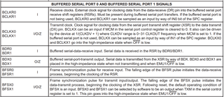
               We are looking for a DSP/Micro controller or a Processor to interface the same TDM port in the DSP of TMS320VC549.

    Please check the image attachment for TDM ports

               Can you help with possible parts ,that has same TDM pin interface (mainly DATA and address are separate pins).

               We found TMS320LC548 has same pin interface but it is 80 MIPS max, Where as we are looking for 100 MIPS and above.

               Based on Our study of TDM Serial interface like IIS, BSP, McBSP & McASP we found that ,they are not meeting the Pin interface requirement for my TDM serial Port in TMS320VC549.

               Can you please comment on the correctness of above statement and if there are any other ways to interface TMS320VC549 TDM serial port to any standard TDM interface it would be very helpful for us to move forward.

              If in case TMS320VC549 TDM port is not available in the current available parts from TI or TI TDM available parts with End of Life < 5+ years.

    Note that other interfacing side part Code changes is not at all possible. 

    Thanks,

    Rajesh..


  • Rajesh, 

    Had to look up the VC549 TDM mode with TADD - have not seen that mode supported in any recent devices.

    If you need to mimic this behavior - you can do it with McASP by using two data pins.   For transmit you would put data into one serializer and the address in a second serializer and transmit both together.   (that should work if you are transmitting to a bank of VC549's).

    If you are receiving data from VC549's that are transmitting an address you can do something similar - use two serializers one to receive data, the second to receive address.   McASP would receive all of the times slots but you could discard the time slots not required by checking the address against that data and throwing away what doesn't match. 

  • Hi Anthony,

    Thanks for your reply

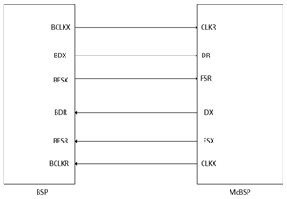
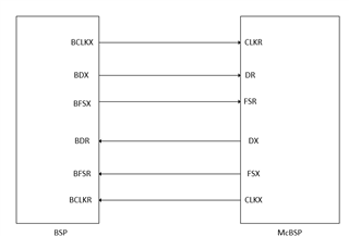
    Please check the image attachment for BSP Ports

    Could you please confirm whether we can use the existing BSP ports in TMS320VC549 as the standard McBSP ports.

    Thanks,

    Rajesh..

  • Rajesh that looks correct, but it isn't using the address protocol that you highlighted in the message you'd sent on 10th. 

    If the TDM scheme you need to interface requires the address and data separately - then the above probably won't work;  then you could use a serial port like McASP with several transmit/receive pins to simulate the address. 

    If you don't need the address - then the above is good.    Hard to say without seeing the exact waveform you're interfacing to. 

    Should also note that we don't have any code examples for this case - the BSP on the VC549 is an early design from 1990s and that mode with the address line I haven't seen on any recent processors/dsps from us.   We've basically standardized on McBSP or McASP as this type of port (where there is a lot of overlap but the McBSP is telecom centric while McASP is audio centric)

  • Hi Anthony,

    I agree with your reply, when interfacing TDM port with McBSP I cannot get address signal. As you said i will be interfacing to McASP only.

    In my system, I have two types of interface

    1. TDM port interfacing with McASP --> this is clear from above replies

    2. BSP port interfacing to McBSP --> Can you conform this alone please ? For this only i had attached image for reference.

    Thanks,

    Rajesh

  • Hi Rajesh,


    Yes I expect the above BSP <> McBSP to work - from a protocol level.   

    Do also check that the IO (voltages, thresholds) are compatible between the VC549 and the device you pick for the right hand side.

  • Hi Anthony,

    Thanks for your reply.

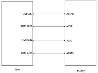
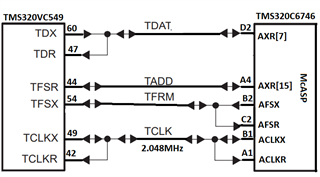
    Please check the image attachment for the TDM to McASP

    As we are planning to connect the TDM DATA and TDM ADD with the two serial data ports of McASP (AXR7, AXR15)

    Can you please comment on the correctness of above statement or if there are any other ways to implement this with (TDM ADD and TDM DATA in seperate ports)

    Note that only two serial data pins(AXR7,AXR15) are available for TDM and remaining data pins are multiplexed with McBSP0 and McBSP1 as we are planning to use those two ports also in our design.

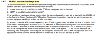
    Please check the image attachment for McASP inactive slot usage.

    Is this going to affect our above configuration.

    Thanks,

    Rajesh..

  • Rajesh, 


    Figure looks good if you are intending to *receive* data from the VC549 in TDM mode.


    For the TDM mode - the VC549 and the McASP are a little different even though both use the term "TDM"

    I don't know how the addresses are generated for VC549.   If they are under software control and they may not come in the same order 

    then what you need to do is (as your figure shows)  on McASP receive every time slot  (none would be 'inactive').

    You will receive more data than you need to so it will push the memory bandwidth and software burden up on the receiver, but a modern device should not have any issue with this.   You then need to post-process. 

       - for every time slot in memory you will have one word from serializer 7 and one from serializer 15. 

        - you will need to discard all of the samples received with an address (received from serializer 15) that you do not want to process on the receiving device. 

    If on the other hand the VC549 transmits the address automatically and in a fixed sequence 0, 1, 2, 3 .. beginning at the frame sync, then you wouldn't actually need to use Serializer 15 - you could use the McASP's inactive time slot feature and program apriori which slots you want McASP to receive. 
    But you need to be aware that the address transmitted is ignored if you do this,  it's a fixed timeslot map 

  • Hello Rajesh, 

    I have not heard from you and closing the thread.

    Regards,

    Sreenivasa

  • Hello Anthony,

    Please check the image attachment for your reference.

    We want this TDM bus to operate in both the ways for transmission as well as reception in the McASP port (AFSX/AFSR), (ACLKX/ACLKR).

    Whether shorting these two pins directly (AFSX and AFSR),(ACLKX and ACLKR) will work or any switch is needed to isolate these pins in McASP.

    Thanks,

    Rajesh..

  • Hi Rajesh, 

    So in the above, the intent is half-duplex communication,  either TMS320VC549 is transmitting and TMS320C6746 is receiving  - or - vice-versa,  at any given moment? 


    Also, is there more than one instance of TMS320VC549 or TMS320C6746 in the system?   (this would seem likely as a reason to use the TADD mode on the 549..) 


    Would be good to expand upon the above diagram w. mode specific diagrams - checking each mode.   So for example if you are wanting half duplex - and that means 2 directions - it would be two diagrams with each diagram's  'arrows' showing the planned direction of the clock and data for that mode.    

    That way we're able to check each mode for drive conflicts.  

    Likewise if there is more than one instance of one of the devices, would be good to draw in at least two of them so we can understand how switching from device 1 to 2 would work.  

    I think once it's understood how the different modes are expected to work and we confirm no drive conflicts (or that some glue is needed to avoid a conflict) then the last question will be how to switch these modes around dynamically.   
    Changing pin directions may require some time. 

  • Hello Anthony,

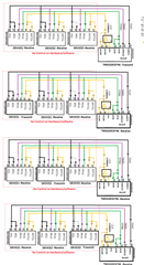
    Please find the attached images for your reference..

    Can you please conform on the Connection made are ok ? mainly GPIO controls the Transmit clock . is this possible without any timing volition?  

    Note: Devices1,2 & 3 are old and defined in software and  hardware . So no changes are possible now .one that can changed is TMS320c6746

    As per old TDM bus architecture changing direction is taken care by DSP itself internally i believe ? please conform

    And also there is no time gap between time slots (they are continuous in time). so changing direction should be happening in Run time without any Glue Logic. please comment/ correct our understanding on TDM bus

    we are using  the document "spru131g" for understanding TDM. Please provide if any other better document is available from TI.

    Thanks,

    Rajesh..

  • Hi Rajesh, 

    Thank you for the inputs.

    Please expect some delay as Anthony reviews the inputs.

    Regards,

    Sreenivasa

  • Hi Rajesh, 

    I looked at the link you sent "spru131g"  and it seems to cover vc549  (page 40 or 1-8 lists it)..  So thanks this is very helpful. 

    From that document: 

    Section 9.3.4 TDM Serial Port Interface Operation
    4th Paragraph:

    "All TDM port operations are synchronized by the TCLK and TFRM signals.
    Each of them are generated by only one device (typically the same device),
    referred to as the TCLK and TFRM source(s)."


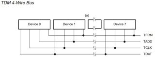
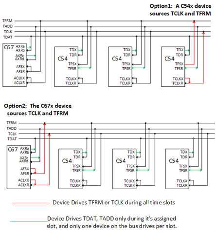
    Therefore, I think your topology is going to look something like one of the two options below: 

    So for your current system if one of the VC549 is driving the TCLK, TFRM lines,  then you'd use option 1 and you'd want to confirm that this VC549 is always driving those lines (it should be per SPRU131g).   If none of the VC549 drive then you can drive from the C67x like Option2 shows. 

    I'm going to use a,b,c,d for some #'s - you can pick these depending on which pins you have available on the C67x ... 

    The C67 would use two serializers AXRa, AXRb for the TDAT line and 2 Serializers AXRc, AXRd for the TADD line. 

    One serializer would be configured as a transmitter for each line  (AXRa for TDAT,  AXRc for TADD) 

    The other pin is always receiving (AXRb receives TDAT and AXRd receives TADD) 

    For the McASP Transmitter,  you would need to program the XTDM with a '1' in the time slots during which you want the 67x to drive.

    You also need to program the XMOD field in AFSXCTL with the # of time slots being used by the VC549's - should be less than or equal to 8.

    Figure 9-34 in section 9.4.6 shows that the VC549 has an equivalent register to 'XTDM' on theC67x -- it's the TCSR register. 

    You can see in that figure that TCSR is set so that only one device on the bus is active in a given timeslot. 

    And in section 9.4.4 it says: 

    "If no device on the TDM bus is configured to transmit in a slot (that is, none of
    the devices has a 1 for the corresponding slot in their TCSR), that slot is
    considered empty. In an empty slot, both TADD and TDAT are high impedance."

    That behavior is also supported by the McASP on C67x -  On a pin-by-pin basis. 

    So for the transmit serializers ( AXRa and AXRc)  you want to make sure to program "DISMOD"  as 0  (drive on pin is 3-state during inactive slot) 


    The McASP Receiver you'd configure a bit differently - it can be active during all the time slots. 

    You'll be receiving on pins AXRb and AXRd and since you need to decode TADD in each slot you need to listen/receive during all the slots. 

    You can discard the data that you don't want to receive.  it looks like the TADD scheme used on the VC549 was a bit mask,   so that one transmitter could set multiple bits in TADD and transmit to multiple devices simultaneously.    That's something you can mimic in software by 'ANDING' the bit # of the C67x with the received TADD. 

    Hopefully this is a start - pls remember I've not actually used a VC549 and only going by the spru131g guide so I'm sure there'll be refinements. 

    It looks like the VC549 has 1 -bit delay from frame sync to first data bit of the next slot .. so you'll want to program the McASP that way (RFMT, XFMT registers have a 'xDATDLY' field... should be a value of 1 in that field. 

    I didn't look at the timing, but McASP on the C67x is a lot faster than the older VC549 - and you would configure the clock polarity so that when the VC549 transmits (say for example on the rising edge of CLKx as showin in the VC549 datasheet  "serial port transmit timing" timing diagram,  then you want the McASP receiver to be configured to receive on the opposite edge (falling edge) so that you've built in a half CLKX cycle of time to work with for setup/hold.

    The biggest pitfall may be the delay from transmitting to HI-Z on the VC594 - if that's 40ns that *might* be a bit long for the C674x and you may have some contention on the shared TDAT, TADD pins to worry about.  I'm not sure how this problem is handled with just the vc549's on the bus though because the spec on DX after CLKX valid is 25ns but the spec on DX 3-state after CLKx is 40ns ..  maybe you have series resistors on these lines already ? 

  • Hi Anthony,

    Thank you very much for your time and the Proposed configuration that you had suggested us. 

    To meet our existing system requirements we need A processor with two McBSP’ s and one McASP peripheral in it. C6746 has these peripherals but they are multiplexed with each other. which means we can't use both at a time. So we finally convinced ourself to use Only one MCASP and one MCBSP alone to meet the above proposed configuration along with the the pin multiplexing within the processor.

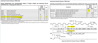
    we had made the analysis of meeting the old TDM timing requirement with the current MCASP timing requirements and we had a conflict in this timings. the same was described below. 

    As per the technical reference manual spru131g document the data transmitted on the rising edge by the transmitter and sampled by the receiver on the rising edge only.

    “Beginning with slot 0 and with the MSB first, the transmitter drives 16 data bits for each slot, with each bit having a duration of one TCLK cycle, with the exception of the first bit of each slot, which lasts only half of one bit time. Note that data is both clocked onto the TDAT line by the transmitting device and sampled from the TDAT line by receiving devices on the rising edge of TCLK (see the data sheet for detailed TDM interface timings).”

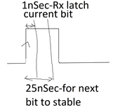
    Considering this requirement we can't no way sample the data at the receiving end on the following edge of the clock cycle. So, now going to the timing requirements mentioned in the old processor Datasheet the hold time maintained by the transmitter is 1 nanosecond from the clock rising edge. whereas this whole time requirement is met by the old TDM receiver which is also of 1 nanosecond from the clock rising edge.

    coming to our case that MC ASP receiver requirements of whole time is minimum of 3 nanosecond from clock rising edge and it's not met by the old TDM transmitter. at the same time we can't sample the data on the falling edge.

    Considering this situation, we need your support on Understanding the transmitter hold time off 1 nanosecond. And there is additionally a delay time td what's given in the Datasheet of 25 nanoseconds for the next bit settled condition. Can we consider this 25nSec previous bit hold time? Can you help us a way forward to solve this timing issue? And can you provide more details on old TDM timing such that we can understand better to design our current system.

    Thanks,

    Rajesh..

  • Hello Rajesh,

    We are reviewing the inputs.

    Regards,

    Sreenivasa

  • Hi Anthony/Sreenivasa,

    Is there any updates regarding my query?

    Thanks,

    Rajesh..

  • Hi Rajesh, 

    Apologies for the slow response. 


    I see two things in the timing diagrams: 

      1) yes there is a mismatch.  my own suggestion would be to add some delay to the VC549 driver for data and addr - around 2-3ns. 

          this may need to be some passive circuit for the data line given that the VC549 is going to 3-state the output at times. 

      2) On the McASP side it appears simplest to capture data on the clock rising edge;  the frame sync to bit clock delay also appears to be

          2 not 1 

    Best Regards,

    Anthony