This thread has been locked.

If you have a related question, please click the "Ask a related question" button in the top right corner. The newly created question will be automatically linked to this question.

TMDS64EVM: BCDMA Transfer Request Descriptor

Part Number: TMDS64EVM

I am using Am64x with No-RTOS. I have a few questions regarding Transfer Request

1. Are we forced to use a specific type of transfer request for the BCDMA? I am using Am64x, Is it obligated to use the TR15 type based on its hardware implementation of it? Because in the TRM and also the examples it is only using TR15 Type. If I use TR15 Type and I only want one dimension, I can simply set the icnt1-3 = 1 and dim1-3 =0?

2.  If I use the BCDMA to move data through GPMC to an external ASIC, Is there any specific limitation/requirement that I should consider for setting the icnt? 

3. can the output event of the TR be the trigger for another transfer request?

4. What is the usage of the wait field? does it mean that we can decide on a transfer request in the same packet to preempt another transfer request?

5. Based on the TRM can have multiple transfer requests in a transfer request packet (Am64x TRM revision 2.0) and the number of times going through them is defined by Reload Count and Reload Index. Does it mean that multiple transfer requests can be assigned to a specific packet (which has a specific corresponding allocated channel number)? meaning that a packet can be shared between different devices for example the same packet corresponding to a specific channel can transfer both from UARTto memory and from ADC to memory.

Thanks, 

Boshra

  • Hi Boshra,

    I am working on your queries.

    Please allow me one or two days to get back to you.

    Regards,

    S.Anil.

  • Did you have the chance to look into it?

  • Hello Boshra,

    Please see my answers below .

    1. Are we forced to use a specific type of transfer request for the BCDMA? I am using Am64x, Is it obligated to use the TR15 type based on its hardware implementation of it? Because in the TRM and also the examples it is only using TR15 Type. If I use TR15 Type and I only want one dimension, I can simply set the icnt1-3 = 1 and dim1-3 =0?

    Yes, these settings will be fine for one-dimensional movement.

    You have to keep values below .

    icnt3 = 1, icnt2 = 1, icnt1 =1 , icnt0 = length and dim 3 to dim 1 = 0. It should work.

    Please go through the below chapter. It would be helpful to learn more about ICNT and DIM value configurations.

    UdmaUtils_makeTrpdTr15 can support all features of other TRs. So, it is mainly used in TRM and software.

     If I use the BCDMA to move data through GPMC to an external ASIC, Is there any specific limitation/requirement that I should consider for setting the icnt? 

    According to my knowledge, the maximum amount of data that can be transferred is 1GB bytes.

    Can you please elaborate on how many bytes you wanted to transfer in one go? This would be helpful, and based on your request, we need to set these icnt and dim values.

    3. can the output event of the TR be the trigger for another transfer request?

    Typically, TR can be configured only once, and  when you want to initiate a new TR, you have to close the UDMA channel and again transfer a new TR request.

    Actually, if you want to trigger  same TR for infinite times without changing any TR descriptor, by using the below function, we can make it work.

    CSL_udmapCppi5TrSetReload

    We can achieve your requirement with the help of DMA chaining . It means that there are two channels: one channel has one TR, and the second channel has a different TR. If one TR event is triggered next, we can trigger the new event. This way, we can achieve your requirements.

    5. Based on the TRM can have multiple transfer requests in a transfer request packet (Am64x TRM revision 2.0) and the number of times going through them is defined by Reload Count and Reload Index. Does it mean that multiple transfer requests can be assigned to a specific packet (which has a specific corresponding allocated channel number)? meaning that a packet can be shared between different devices for example the same packet corresponding to a specific channel can transfer both from UARTto memory and from ADC to memory.

    By using reload count and reload index, you can select how many times data should be transferred from source memory to destination memory.

    Let say If you want to transfer data from ADC memory (MSRAM) to UART memory (MSRAM) for infinite times, you have to configure the Reload Count value as 0x1FF, and you have to specify after each TR transfer, DMA where to select the index value of the source buffer for the next iteration .

    CSL_udmapCppi5TrSetReload

    By using the above function, you can achieve your requirement.

    Can you please elaborate exactly what application you are going to implement? So that it would be helpful us to better assist you?

    Regards,

    S.Anil.

  • Thanks for your reply, it was helpful to clarify.

    As more information for our case, We are using AM64x and we want to connect it to our ASIC. Our ASIC is containing ARINC, DSP, HQIetc. 

    We want to use GPMC to transfer and receive data to/from DSP:

    Each 700us sends to ASIC (DSP) 2500 byte

    Each 700us receives from ASIC (DSP)2500 bytes

    Each 50ms sends to ASIC 

    Each 50ms receives from ASIC

    and etc. 

    For the above-mentioned transfers, I  want to use the BCDMA block copy.

    Also, we want to use DMASS for UART(s), SPI, and Ethernet. My understanding based on the TRM is that for Ethernet we should use PKTDMA, but for the SPI and UART I can choose either PKTDMA or BCDMA. 

    However, I don't understand when we use PKTDMA and when we use BCDMA. Is PKTDMA mainly used when we have scatter & gather (sent to many different destinations/or from many different sources in the memory)? 

    In the case of using PKTDMA (e.g. using UART rx to memory) does the host/descriptor packets are also sent to the memory or only the data buffer is loaded the memory?

    Also, I would like to know in case of bursting in BCDMA, how this burst is sent into the bus? is it done for each byte of data an address sent as well? or the length is sent and then based on the length the ASIC should expect a number of bytes to receive?

    Also, Do you have any documentation that explains what algorithm TI used for sharing the DMA and Bus? I didn't find this information documented anywhere. We would like to do some analysis for bus terrific to set the proper order and priority for each transfer in our case. However, it's not clear to me what algorithm you have used for sharing the bus and DMA. For example, I don't know how the following fields of the registers are set and what is the usage of them in your algorithm, what is the difference between DMA priority and Bus priority? why these are not the same(it's not that the DMA transfers each channel data to the bus? or do we need DMA priority to first fill the data in its internal fifo using DMA priority and then from the FIFO to bus using bus priority? why do we need two priorities and what is the usage of each of them)? 

    - Priority field of: DMASS0_BCDMA_0_PRI_CTRL Register

    - Order ID of : DMASS0_BCDMA_0_PRI_CTRL Register

    - Priority field of: DMASS0_BCDMA_0_ST_SCHED

    In our case, setting the priorities that the DMASS transfers are done is very important to make sure we have all the data we need to transfer at the right time and order. 

    Thanks,

    Boshra

  • Hello Boshra,

    Thanks for sharing your request.

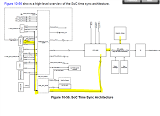
    I can say that for your approach, we can go with DMA auto-triggering since timing constraints are there in your requirement .

    Please look at the image below and check more details for DMA auto triggers.

    What we can do is divide into two UDMA channels. One is the TX channel, and the other is the RX channel.

    TX channel: sending data from SOC to ASIC for different time intervals

    That timing interval can be configured in the IEP comparators. Total AM64X has 8 comparators, so you can configure 8 time events, and based on those values, DMA will be triggered automatically.


    RX channel: Read data from the ASIC to the SOC for different time intervals.

    That timing interval can be configured in the IEP comparators. Here you can use a different comparator module, i.e., IEP1.

    All AM64Xs have 8 comparators, so you can configure 8 time events, and based on those values, DMA will be triggered automatically.

    I have attached the basic example code for the above approach for your reference.

    iep_triggers_memcpy.zip

    However, I don't understand when we use PKTDMA and when we use BCDMA. Is PKTDMA mainly used when we have scatter & gather (sent to many different destinations/or from many different sources in the memory)? 

    In the case of using PKTDMA (e.g. using UART rx to memory) does the host/descriptor packets are also sent to the memory or only the data buffer is loaded the memory?

    Please see my answers below .

    Block Copy DMA (BCDMA): Block copy refers to a simple method of copying a contiguous block of data from one location in memory to another. This method is typically used when you want to transfer data between memories.

    Packet DMA (PCKTDMA): This is a hardware-based method for transferring data between memory and peripheral devices such as Ethernet interfaces, SPI, UART, and ADC, etc.

    In packet DMA transfers, the peripheral device sends a request to the DMA controller to transfer a certain amount of data from memory to the device or vice versa.

    Also, Do you have any documentation that explains what algorithm TI used for sharing the DMA and Bus? I didn't find this information documented anywhere. We would like to do some analysis for bus terrific to set the proper order and priority for each transfer in our case. However, it's not clear to me what algorithm you have used for sharing the bus and DMA. For example, I don't know how the following fields of the registers are set and what is the usage of them in your algorithm, what is the difference between DMA priority and Bus priority? why these are not the same(it's not that the DMA transfers each channel data to the bus? or do we need DMA priority to first fill the data in its internal fifo using DMA priority and then from the FIFO to bus using bus priority? why do we need two priorities and what is the usage of each of them)? 

    - Priority field of: DMASS0_BCDMA_0_PRI_CTRL Register

    - Order ID of : DMASS0_BCDMA_0_PRI_CTRL Register

    - Priority field of: DMASS0_BCDMA_0_ST_SCHED


    I think it is very difficult to get this information from IP owners for algorithm in between DMA and BUS.

    But I can check with them and let you know.

    In our case, setting the priorities that the DMASS transfers are done is very important to make sure we have all the data we need to transfer at the right time and order. 

    I think if you are following my proposed method, it will make sense and you will not bother about order and sequence.

    Please close this thread if you don't have any other questions and open new threads if you do.

    Regards,

    S.Anil.

  • Hello Boshara,

    As of now, the GPMC peripheral driver is not available on the Am64X MCU +SDK . How are you going to achieve GPMC peripheral?

    Are you implementing GPMC peripheral by yourself?

    Regards,

    S.Anil.

  • Hi, Thanks for your reply. 

    Regarding BCDMA vs. PKTDMA, there are some FIFOs in the BCDMA that are connected to remote peripherals through PSIL. So my understanding is that still I will be able to use BCDMA Split mode for UART, SPI, etc. 

    About GPMC, I know the driver doesn't exist for AM64X windows, However, it exists for some other models. So we were planning to write the driver ourselves based on an existing one and use it through DMA as a block copy (memory to memory). To me, it seems the underlying channel and ring allocation on the DMA side are not dependent on the GPMC driver, so we will be still able to use the Tisci services on the dma side for channel allocation, etc. And for the GPMC side, I didn't have to take a look at the existing driver for a Linux-based version, but if the underlying services exist, we should be able to write the driver ourselves. Do you see is feasible?  

    Or did you mean the Hardware peripheral doesn't exist on AM64x?

    Thanks, 

    Boshra

  • Regarding BCDMA vs. PKTDMA, there are some FIFOs in the BCDMA that are connected to remote peripherals through PSIL. So my understanding is that still I will be able to use BCDMA Split mode for UART, SPI, etc. 

    Hello Boshra,

    Yes, your understanding is correct. You can use BCDMA for UART and SPI; there is no problem at all.


    About GPMC, I know the driver doesn't exist for AM64X windows, However, it exists for some other models. So we were planning to write the driver ourselves based on an existing one and use it through DMA as a block copy (memory to memory). To me, it seems the underlying channel and ring allocation on the DMA side are not dependent on the GPMC driver, so we will be still able to use the Tisci services on the dma side for channel allocation, etc. And for the GPMC side, I didn't have to take a look at the existing driver for a Linux-based version, but if the underlying services exist, we should be able to write the driver ourselves. Do you see is feasible?

    I think in the PROCESSOR SDK AM64X I am not aware whether GPMC peripheral is aviable or not. You can check in the AM62X SOC and the GPMC driver is already available on A53. In my view, both GPMC IPs are almost the same. See if you can try to use it in AM64X if the GPMC driver is not available on AM64X MCU+SDK.

    Yes, your understanding is correct. DMA channel allocation and ring allocation are independent of the GPMC driver.

    Or did you mean the Hardware peripheral doesn't exist on AM64x?

    NO .. I am mainly talking about the GPMC software driver, and the GPMC peripheral is available on the AM64X.

    Regards,

    S.Anil.

  • I think it is very difficult to get this information from IP owners for algorithm in between DMA and BUS.

    But I can check with them and let you know.

    Hi, Did you have the chance the verify it? Also, I would like to know who is doing the arbitration on the BUS. Is it DMSC(core M3) who is doing that?

    Thanks, 

    Boshra

  • Hello Boshra,

    As per my knowledge, UDMA can support burst mode to access the CPU bus, and I am not aware of any other modes that can be supported by UDMA. I sent a message to the system team. Once I receive the response, I will update you. 

    Arbitration should be controlled by the MAIN domain (R5F/A53) only, and DMSC does not do these types of operations. The DMSC core mainly does reset, clock, power ,Firewall configurations , Resource Allocation and security.

    Regards,

    S.Anil.

  • Also

    Also about the registers that set the bus order, DMA priority, and bus priority, these are some registers that appeared as some parts of the structs that need to be set and used by the driver, if I don't know how they are used, and what they mean, how I can use them. I didn't find any information on how these values are used... do you have documentation for them?

  • Also about the registers that set the bus order, DMA priority, and bus priority, these are some registers that appeared as some parts of the structs that need to be set and used by the driver, if I don't know how they are used, and what they mean, how I can use them. I didn't find any information on how these values are used... do you have documentation for them?

    Hello Bishra,

    As of now, the UDMI driver is not controlling these registers, and by default, these registers have zero values. I think they are following the round-robin technique.

     I also don't have documentation on this topic. I will check with the system team and update you on the status.

    I got a reply from the System Team, as they mentioned the UDMI driver is following only the Burst mode.

    Regards,

    S.Anil.

  • As of now, the UDMI driver is not controlling these registers, and by default, these registers have zero values. I think they are following the round-robin technique

    Yes, I know the default values are set in the driver, but we have the possibility to change these values, so what is each of these registers representing? what is the difference between DMA priority and BUS priority? is DMA priority only the priority for copying the values into an internal buffer? or its sth else? and then the BUS priority. 

    I got a reply from the System Team, as they mentioned the UDMI driver is following only the Burst mode.

    I don't understand this sentence is the answer for which question?

  • Yes, I know the default values are set in the driver, but we have the possibility to change these values, so what is each of these registers representing? what is the difference between DMA priority and BUS priority? is DMA priority only the priority for copying the values into an internal buffer? or its sth else? and then the BUS priority.

    Hello Boshra,

    I agree with your points.

    I can request a mail to the system engineer to get the document on your request and will update the status.

    I don't understand this sentence is the answer for which question?

    As per my knowledge, UDMA can support burst mode to access the CPU bus, and I am not aware of any other modes that can be supported by UDMA. I sent a message to the system team. Once I receive the response, I will update you

    I have confirmed above comments with SYSTEM engineer .So, UDMA supports only Burst mode when it accessing the CPU bus .

    Regards,

    S.Anil.