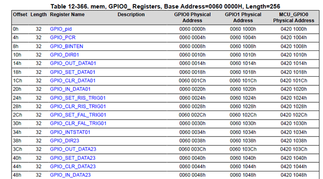
I need the gpio number to set the interrupt pin of the touchscreen i2c interface, please refer to the two links provided below.
AM625: Confusion about GPIO of MAIN Domain
Thanks,
Andrew
This thread has been locked.
If you have a related question, please click the "Ask a related question" button in the top right corner. The newly created question will be automatically linked to this question.
I need the gpio number to set the interrupt pin of the touchscreen i2c interface, please refer to the two links provided below.
AM625: Confusion about GPIO of MAIN Domain
Thanks,
Andrew
Hello Andrew
Thank you for the query.
The GPIO information mapped to the device pins is available in the data sheet.

Please elaborate your requirement.
Regards,
Sreenivasa
Hi Kallikuppa,
Thanks for your reply.
I have to use the gpio number in both places.
1. It is necessary to read and write gpio to determine the lvds panel dts to be imported. I have previously released a thread on this part of the requirements.
2. The setting of i2c touchscreen pin, below is the touchscreen driver segment given by the panel manufacturer, and I want to use I2C1 and set GPIO1_31 as interrupt pin, what are I2C_BUS_NUMBER and GPIO_INT?
#define I2C_BUS_NUMBER		2						//TODO: modify to set your I2C Bus
#define GPIO_INT			80//GPIOB(16)			//TODO: modify to set your INT pin
#define GPIO_IRQ			gpio_to_irq(GPIO_INT)	//TODO: modify to set your IRQ number
So I need a method of calculating GPIO_NUMBER or a comparison table.
Thanks,
Andrew
Hello Andrew,
Thank you.
Please help me understand the development environment you are using.
regards,
Sreenivasa
Hello Andrew,
Thank you.
Please read through the below sections in the data sheet and TRM.
Data sheet
6.3.11 GPIO
6.3.11.1 MAIN Domain
Table 6-23. GPIO0 Signal Descriptions
GPIO_0..91
Table 6-24. GPIO1 Signal Descriptions
GPIO_0..51
6.3.11.2 MCU Domain
Table 6-25. MCU_GPIO0 Signal Descriptions
MCU_GPIO0_0..23
TRM
6.1.2 Pad Configuration Register Modules
6.1.2.3 Pad Configuration Ball Names
Table 6-2046. Pad Configuration Ball Names
12.2.1 General-Purpose Interface (GPIO)
Table 12-259 describes the GPIO I/O signals.
Table 12-259. GPIO I/O Signals
12.2.5 General Connectivity Registers

Each register is 32 bit - 0..31 GPIOs.
You can find the GPIO required and then calculate the register using the above sections of the data sheet or TRM.
Let me know if this helps.
Regards,
Sreenivasa