This thread has been locked.

If you have a related question, please click the "Ask a related question" button in the top right corner. The newly created question will be automatically linked to this question.

TMS320C6678: There is a certain delay between the CPU and external devices, which may be due to internal limitations of the CPU

Part Number: TMS320C6678
Other Parts Discussed in Thread: AMC7812

 if(cs == 0) {
        spiRegs->SPIDELAY = (8 << CSL_SPI_SPIDELAY_C2TDELAY_SHIFT) |
                        (8 << CSL_SPI_SPIDELAY_T2CDELAY_SHIFT);   //(8+1)*6ns=54ns
        /* default chip select register */
        spiRegs->SPIDEF = CSL_SPI_SPIDEF_RESETVAL;     //T2C END TO CHIP SELECT ; C2T CHIP SELECET TO START
    } else if(cs == 1) {
        spiRegs->SPIDELAY = (6 << CSL_SPI_SPIDELAY_C2TDELAY_SHIFT) |   //7*6ns=42ns  4*6ns=24ns
                        (3 << CSL_SPI_SPIDELAY_T2CDELAY_SHIFT);
    }
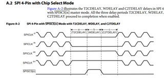
The delay of C2T and T2C can be understood as chip selection time and chip selection hold time, resulting in clock after time or clock end time delay.
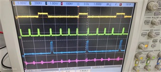
But my concern is why the WDELAY time in the timing chart is so large, as shown in the picture at 780ns.
In the DEMO program, SPI_SPIFMT.WDELAY does not have a time set, and the default value of the register is 0. And with the default value of 0 for SPI_SPIDAT_1 WDEL, why does the CS switching time for each frame of data take 780ns?
Now the core board circuit is fully encapsulated, not open to the public, and cannot be rectified. We directly introduce SPI data cables from the core board circuit for timing testing. Now I want to know why the hardware circuit is not executed according to the software settings?
Our project now requires an interruption time of 3.3us to complete multiple SPI controls, and this delay in project design cannot be accepted

Suspect that there is a delay when the CPU accesses the external device. Every time the transmission is retransmitted, there is a certain delay between the CPU and the external device. Is it due to internal limitations of the CPU.
  • Dear Customer,

    Let me experiment the SPI of C6678 and let me come up with the number of CPU cycles taken and the time measurement during SPI transmission.

    Expect results in a day or two.

    Regards

    Shankari G

  • HI 

      pdk_c6678_1_1_2_6/packages\ti\platform\env6678l\paltform_lib\src

    spi_xfer
    (
    uint32_t nbytes,
    uint8_t* data_out,
    uint8_t* data_in,
    Bool terminate
    )
    {
    uint32_t i, buf_reg;
    uint8_t* tx_ptr = data_out;
    uint8_t* rx_ptr = data_in;

    /* Clear out any pending read data */
    SPI_SPIBUF;

    for (i = 0; i < nbytes; i++)
    {
    /* Wait untill TX buffer is not full */
    while( SPI_SPIBUF & CSL_SPI_SPIBUF_TXFULL_MASK );
    /* Set the TX data to SPIDAT1 */
    data1_reg_val &= ~0xFFFF;
    if(tx_ptr)
    {
    data1_reg_val |= *tx_ptr & 0xFF;
    tx_ptr++;
    }

    /* Write to SPIDAT1 */
    if((i == (nbytes -1)) && (terminate))
    {
    /* Release the CS at the end of the transfer when terminate flag is TRUE */
    SPI_SPIDAT1 = data1_reg_val & ~(CSL_SPI_SPIDAT1_CSHOLD_ENABLE << CSL_SPI_SPIDAT1_CSHOLD_SHIFT);
    } else
    {
    SPI_SPIDAT1 = data1_reg_val;
    }

    /* Read SPIBUF, wait untill the RX buffer is not empty */
    while ( SPI_SPIBUF & ( CSL_SPI_SPIBUF_RXEMPTY_MASK ) );
    /* Read one byte data */
    buf_reg = SPI_SPIBUF;
    if(rx_ptr)
    {
    *rx_ptr = buf_reg & 0xFF;
    rx_ptr++;
    }
    }
    return SPI_EOK;
    }

    1、May I ask what are the functions of while (SPI-SPIBUF&CSL_SPI-SPIBUF-TXFULL_MASK) and while (SPI-SPIBUF&(CSL_SPI-SPIBUF-RXEMPTY-MASK) in this function?
    2、Is it necessary to add a waiting time to ensure SPI data synchronization for reading and writing data?

  • Is there a delay between multiple bytes in SPI frame data?

  • The engineer responsible is currently out of the office. Please expect a 1-2 day delay in response.

    Thanks.

  • Dear Customer,

    I have finished my experiments on SPI READ and SPI WRITE.

    Calculated the number of CPU cycles consumed.

    Please find the details below.

    SPI READ:- 

    ========

    Experimented with 65536 bytes of data-read. It takes "0.066 seconds" 


    Started at cpu cycle = 599574093 cycles


    Ended at cpu cycle = 666070777 cycles


    Total_cpu_cycle of [SPI Read of 65536 bytes ] = 66496684 cycles 

    In my C6678 TI EVM - The DSP is running at a core frequency of 1000 MHz.

    (DSP core frequency = 1000 MHz)


    Time = 1 / Freq ( General formula )

              = 1 / 1000 MHz ( DSP core frequency )

              = 0.001 us ( Micro seconds) 


    1000000000 cycles = 1 sec

    =>66496684 cycles =  0.066 sec

    SPI WRITE:-

    =========

    Experimented with 65536 bytes of data-read. It takes "1.007 seconds" 

    Started at cpu cycle = 1421661660 cycles

    Ended at cpu cycle = 2429013489 cycles

    Total_cpu_cycle of [ SPI Write of 65536 bytes ] = 1007351829 cycles


    Regards

    Shankari G

  • The test result above reads 65536 bytes and uses 0.066s
    Is a byte 8 bits?
    Does the above data test whether CS has been consistently maintained? Switching time without CS.

  • Is a byte 8 bits?

    yes.

    Does the above data test whether CS has been consistently maintained? Switching time witho

    CS, you mean chip select?  ---> yes. It is.

    Interfaced with NOR memory------> PLATFORM_DEVID_NORN25Q128       0xBB18    /**< 16MB NOR Flash */

    SPI Flash --- "NOR 128M-bit N25Q128A21BSF40F" 

    --

    NOR Device:
    p_device->device_id = 47896
    p_device->manufacturer_id = 32
    p_device->width = 8
    p_device->block_count = 256
    p_device->page_count = 256
    p_device->page_size = 256
    p_device->spare_size = 0
    p_device->handle = 47896
    p_device->flags = 0
    p_device->bboffset = 0
    platform_device_close(handle=0xbb18) called
    platform_device_open(deviceid=0x50,flags=0x0) called

    Regards

    Shankari G

  • Hi,Shankari G

    Thank you for your test results.
    The estimated time to read a data is 66000000/65535=1007ns.
    nor flash clk in the code is 25M, period 40ns? In theory, reading a byte (8bits) =(8+2)*40=400ns, why does the CPU take 1007ns?
    How long does it take? Is it a delay between bytes? In our tests, we found not only byte delay but also CS switching delay(780ns).

    Test Method When the NOR Flash continuous frame write address CMD=0x9f is simulated to write data, the oscilloscope waveform is read.

  • XING,

    I have not looked into the theoretical value.

    Let me relook.

    Regards

    Shankari G

  • Shankari G,

    Thank you very much.

    Due to the developed product function, the SPI (30M SPI CLK) control TPIC2060 (TI motor IC) was implemented five times in the interrupt cycle (3.3us), and the interrupt execution timeout was found in the test.
    If this issue is resolved, subsequent functionality cannot be implemented. The project is aborted, please help analyze and solve it.

    Regards

    Xing

  • XING,

    I am planning to do the following in the upcoming days. You can also try the same.

    1. DSP frequency to set - From 1000 MHz to 1200 MHz.

    2. Increasing the "SPI_MAX_FREQ            25000000" 

    3. Altering the SPI paremeters like Delay settings etc..

     I will let you know, if I observe any improved data rate in SPI read and write.

    Thanks for your patience.

    Regards

    Shankari G

  • Shankari G,

    The holiday has ended and I will start working today.  

    Because it was my first time encountering DSP ICs, there were many things I understood.

    The following test is only my own testing method and results, but it must be correct. Please understand!

    In the instruction manual of C6678 IC:

    Eight TMS320C66xTm DSP Core Subsystems (C66x CorePacs), Each with – 1.0 GHz, 1.25 GHz, or 1.4 GHz C66x 

    May I ask why the CPU frequency is not set to 1250MHz?

    In code testing:

    Device Speed Register (DEVSPEED)

    #define DEVSPEED (*(unsigned int *)0x026203F8u)

    Device speed grade = 1250MHz.


    Software code settings:

    DSP frequency to set 1250 MHZ

    Increasing the "SPI_MAX_FREQ            10000000" 

     SPI  scalar = ((spi_iclk / freq) - 1 )& 0xFF;

    spi_iclk =10M,freq=gDSP_Core_Speed_Hz/6,

    unsigned int gDSP_Core_Speed_Hz=   1250000000; 

    SPI PRESCALE= 19 

    spiRegs->SPIFMT[0] = (8 << CSL_SPI_SPIFMT_CHARLEN_SHIFT) |
    (scalar << CSL_SPI_SPIFMT_PRESCALE_SHIFT)

    The SPI CLK under the oscilloscope changes to 8.3333MHz. SPI CLK did not approach 10MHz

    Regards

    Xing

  • DSP frequency to set 1200 MHZ

    Increasing the "SPI_MAX_FREQ            25000000" 

    SPI_init: SPI PRESCALE= 7 

    The SPI CLK under the oscilloscope changes to 20.833MHz. 

  • The delay between bytes (8 bits) is 690ns, and the delay for a data frame ( CS switching delay )is also about 690ns.

  • XING,

    As mentioned in my previous post, I am altering the SPI delay and the module clock and experimenting...

    Will let you know the results soon.

    Regards

    Shankari G

  • Hey XING,

    Of course, we can set the DSP core frequency as 1250 MHz.

    Between, Good news to you.

    I could achieve upto some 490 ns for SPI READ.

    Will give the details shortly after running few tests with confirmation.

    Regards

    Shankari G

  • Hey XING,

    Theoretical calculation :- 

    SPI module clk in the code is 25M, i.e, period ----> 40ns

                           1 / 25000000 Hz = 40 Nano seconds for 1 bit of transmission.

                         Theoretically,  for 65536 bytes ---> 65536 x 8 x40 ns = 20971520 ns

    1250000000 cycles  = 1 second ----> when the DSP core runs at 1250 MHz.

    26214400 cycles    = 20971520 ns 

    i.e., 26214400 CPU cycles for 65536 bytes of transmission  - OR - 40 Nano seconds for 1 bit 

    Practical Data Rate:-

    SPI READ TEST - CPU CLOCK CYCLE - Measurement
    ==============================================

    Started at cpu cycle = 598005431 cycles
    Ended at cpu cycle = 647161553 cycles
    Total_cpu_cycle of [SPI Read of 65536 bytes ] = 49156122 cycles

    1250000000 cycles  = 1 second ----> when the DSP core runs at 1250 MHz.

    49156122 cycles      =      0.039  seconds  for 65536 bytes of SPI read.

             ======>    ( 1 / 1250000000 ) x 49156122  = 0.039 seconds.     ---- > 65536 bytes

                                                                                       =====> 0.039 seconds for 524288 bits.

                                                                                       =============> 0.039 / 524288 = 74 ns for 1 bit --- > practically


    Here, out of 49156122 cycles =  26214400 + CPU cycles utilized / consumed to execute the software code ( in terms of instructions to do the SPI transmission )

    At the max, I can achieve 0.039 seconds for 65536 bytes. OR in other words, 1.6 MB /sec  or 1680 KB/ sec ---> SPI READ with 8 byte as Char length with NOR device, N25Q128A21BSF40F.

    ---

    As far as I could improve, I could achieve only this much. It does not mean this is an idle one.

    There might be possibilities to optimize the driver code, which I leave it to the customer's choice.

    ---

    List of changes I did....

    #define SPI_MODULE_CLK 250000000
    #define SPI_MAX_FREQ 65000000 /* SPI Max frequency in Hz */

    1. Removed the spi_delay() function through out the code.

    2. Removed the register settings for Delay in spi_claim()

    // SPI_SPIDELAY = (8 << CSL_SPI_SPIDELAY_C2TDELAY_SHIFT) |
    // (8 << CSL_SPI_SPIDELAY_T2CDELAY_SHIFT);

    3. changed the following in spi_claim () ( Please note, I used Chip select ---> 0 )  

    if ( cs == 0) {


    // SPI_SPIFMT0 = (8 << CSL_SPI_SPIFMT_CHARLEN_SHIFT) |
    // (scalar << CSL_SPI_SPIFMT_PRESCALE_SHIFT) |
    // (CSL_SPI_SPIFMT_PHASE_DELAY << CSL_SPI_SPIFMT_PHASE_SHIFT) |
    // (CSL_SPI_SPIFMT_POLARITY_LOW << CSL_SPI_SPIFMT_POLARITY_SHIFT) |
    // (CSL_SPI_SPIFMT_SHIFTDIR_MSB << CSL_SPI_SPIFMT_SHIFTDIR_SHIFT);


    SPI_SPIFMT0 = (8 << CSL_SPI_SPIFMT_CHARLEN_SHIFT) |
    (scalar << CSL_SPI_SPIFMT_PRESCALE_SHIFT) |
    (CSL_SPI_SPIFMT_PHASE_NO_DELAY << CSL_SPI_SPIFMT_PHASE_SHIFT) |
    (CSL_SPI_SPIFMT_POLARITY_LOW << CSL_SPI_SPIFMT_POLARITY_SHIFT) |
    (CSL_SPI_SPIFMT_SHIFTDIR_MSB << CSL_SPI_SPIFMT_SHIFTDIR_SHIFT);

    ----

    -------

    For SPI write, I could achieve upto 0.75 seconds for 65536 bytes i.e., 87 KB/sec.

    -----( PS: - Not much attention given for SPI write compared to SPI read. )

    SPI WRITE TEST - CPU CLOCK CYCLE - Measurement
    ==============================================
    Started at cpu cycle = 1385879698 cycles
    Ended at cpu cycle = 2331075093 cycles
    Total_cpu_cycle of [ SPI Write of 65536 bytes ] = 945195395 cycles

    1250000000 cycles  = 1 second ----> when the DSP core runs at 1250 MHz.

    945195395 cycles      =        seconds  for 65536 bytes of SPI read.

             ======>    ( 1 / 1250000000 ) x 945195395 = 0.75 seconds. 

    List of changes:

    Removed the delay in nor_write() function.

    // loopCount = 4000; //shankari
    // loopCount = 400;
    // while (loopCount--) {
    // asm(" NOP");
    // }

    ---

    Regards

    Shankari G

  • Hi Shankari G,

    Thank you very much for testing the data.

    Please help me check below to confirm if the test results are understood correctly?

    Debugging conditions:

    when the DSP core runs at 1250 MHz.

    SPI module clk in the code is 25M, i.e, period ----> 40ns

    Final optimization test results:

    1、Total_cpu_cycle of [SPI Read of 65536 bytes ] = 49 156 122 cycles

    49156122 cycles      =      0.039  seconds  for 65536 bytes of SPI read.

             ======>    ( 1 / 1250000000 ) x 49156122  = 0.039 seconds.     ---- > 65536 bytes

             =====> 0.039 seconds for 524288 bits.

            =============> 0.039 / 524288 = 74 ns for 1 bit --- > practically

    2、Total_cpu_cycle of [ SPI Write of 65536 bytes ] = 945195395 cycles

    945195395 cycles      =     seconds  for 65536 bytes of SPI read.

    (I feel like there was a typo in this part. Should it be like this:

    945195395 cycles      =    0.75 seconds  for 65536 bytes of SPI write. )

             ======>    ( 1 / 1250 000 000 ) x 945 195 395 = 0.039 seconds. 

    ( ( 1 / 1250 000 000 ) x 945 195 395 = 0.075 seconds. )

        =============> 0.075 / 524288 = 143 ns for 1 bit --- > practically(Should this be the case here?)

    Regards

    Xing

  • XING,

    (1/1250000000 ) x 945195395 = 0.75 seconds. ==>  

    It cannot be 0.075 seconds.

    :-) 

    Please re-do the calculation.

    Regards

    Shankari G

  • Hi Shankari G,

    I'm really sorry, I miscalculated.

    Is the test result like this?

    1、Total_cpu_cycle of [SPI Read of 65536 bytes ] = 491 56 122 cycles

    49156122 cycles      =      0.039  seconds  for 65536 bytes of SPI read.

             ======>    ( 1 / 1250000000 ) x 49156122  = 0.039 seconds.     ---- > 65536 bytes

            =====> 0.039 seconds for 524288 bits.

            ====> 0.039 / 524288 = 74 ns for 1 bit --- > practically

    2、Total_cpu_cycle of [SPI Write of 65536 bytes  ] = 945 195 395 cycles

    945195395 cycles   =   0.75 seconds  for 65536 bytes of SPI read.

       ======>    ( 1 / 1250000000 ) x 945195395 = 0.75 seconds.          ---- > 65536 bytes

       =====> 0.75 seconds for 524288 bits.

      ====> 0.75 / 524288 = 1430 ns

    Regards

    Xing

  • Hi Shankari G,

    The test results of C6678 platform show that the SPI transmission function is normal, but the transmission speed is not the theoretical calculation speed. According to the needs of the company project, I want to solve the problem of SPI transmission delay. Therefore, I hope TI technology can provide some solutions or continue to analyze the problem, and we will find ways to solve the problem after the specific positioning of the problem.

    According to the above test results:

    N25Q128A21BSF40F ic instruction manual Read Data Bytes (READ)(SPI_NOR_CMD_READ) timing:

    According to the figure above, there is no CS switch when DSP continuously sends data. The reason why 75ns sends 1 bit is probably due to the delay between every 8 bits of data, which is confirmed by the SPI timing waveform in the picture of the chat record above.

    In theory, there is a delay between each byte: 75-40=35ns,35*8=280ns

    In spi_claim() SPIFMT[0].wdelay is not set and should be the register default of 0, so there should be no delay between bytes.

    Now if the DSP operates at 1GHZ and the SPI peripheral works at 1/6 frequency division, the two operating frequencies are not the same. To ensure synchronization, SPI_SPIBUF.TXFULL and SPI_SPIBUF.RXEMPTY bits are added to the spi_xfer () function to wait for judgment bits before SPI data is read and written. Is that the mechanism?

  • XING,

    I understand your point....

    There is no SPI internal expert in TI now for this older device- C6678 to work along with you to further analyze..

    The current SPI write data rate of 1.44 Micro seconds are not sufficient for you ? as your project interruption time requirement is 3.3us ? ( as per your first original port above? ) 


    Regards

    Shankari G

  • Hi Shankari G,

    Due to the high real-time requirements of the developed products, 3.3us cycle interruption was generated using the DSP internal timer, during which four TPIC2060 IC data writes and one AMC7812 read or write were scheduled to be completed.

    Now our test results for this problem are the same. The reason for the delay is basically the time spent waiting for the change of SPI_SPIBUF.TXFULL and SPI_SPIBUF.RXEMPTY bits. However, in order to ensure the synchronization of DSP C6678, the user has no way to solve this problem.

    Is TI C6678 still being shipped? If it is still being shipped, could you please help to consult an expert in this field?
    Are there products with the same architecture as C6678 Keystone 1? If yes, could you help me consult an expert for this problem?

    Regards

    Xing

  • XING,

    Is TI C6678 still being shipped? If it is still being shipped, could you please help to consult an expert in this field?

    Yes. It is being shipped till date. But the support is almost NIL.

    I am looping in our another expert, Praveen Rao who will help you understand the situation better.

    Are there products with the same architecture as C6678 Keystone 1? If yes, could you help me consult an expert for this problem?

    Yes, Keystone II devices like K2E, K2H uses the same architecture of C66x..... 

    But for Keystone III, they moved to C7x architectures...

    Praveen Rao - Whom I looped in, may point out, an internal expert or he may help you to pursue other TI processor devices with high speed SPI or QSPI etc... 

    Regards

    Shankari G

  • Hi Xing,

    As Sankari explained, there would be limited support on these C6678 device. Please note that we do not have any dev support on this device as all the expert have move on to newer J7 devices and/or not in the company anymore. Suggest contacting your local TI sales team so that they can suggest the new device family that you can evaluate for your product.

    Thanks.

  • Hi Praveen Rao, 

    The old product support is understandably weak. However, the product is being shipped. Your company's technical support test and I both found that the SPI module transmission speed has a timeout phenomenon.
    The SPI module comes with LOOPBACK mode. Can you test whether the SPI transmission speed is normal in this mode? If it is not normal, it means that the product is not suitable for us, and I can consider changing the platform again.

    Thanks.

    Regards

    Xing

  • XING,

    We found out just the SPI DATA rate when interfaced with a particular NOR memory flash.

    There is no timeout phenomenon.

    The C6678 SPI transmission is successful with data verification and the SPI transmission is consistent and reliable.

    :-)

    Regards

    Shankari G

  • Hi Shankari G,

    Sorry, I may have expressed the content may be wrong.
    Is that how it should be expressed? The underlying SPI code provided by TI can realize NOR Flash data reading and writing, but users feel that there are problems with the transmission speed or throughput rate, and request TI for technical support or performance verification.
    For the following reasons:
    In the SPI control code provided by TI, we shield the C2TDELAY and T2CDELAY Settings of C6678 according to the instruction manual of KeyStone Architecture Serial Peripheral Interface provided by TI. The default value of SPIFMT.wdelay is 0. The SPI module (SPI CLK =25MHZ(40ns)) continuously sends bytes with a throughput rate of 13.5Mbps(above test result: 74 ns for 1 bit -- > practically).

    Regards

    Xing

  • XING,

    OK, Fine.

    but users feel that there are problems with the transmission speed

    I think, no problem with the transmission speed/throughput rate. That is the maximum it could achieve with the current sample SPI driver and the NOR device selected.

    ---

    Perhaps, the SPI driver shall be optimized by the customer and improve upon.

    Because, usually the sample drivers (SPI )  are provided just for a "proof of concept" to demo the functionality of the interfaces such as SPI etc...

     ---

    In general customers will take the sample code of TI and modify, optimize and improve upon to adapt to their project needs and requirement.

    ---

    Please contact your local TI sales team so that they can suggest new device family that you can evaluate for your product.

    Regards

    Shankari G