This thread has been locked.

If you have a related question, please click the "Ask a related question" button in the top right corner. The newly created question will be automatically linked to this question.

AM62A7-Q1: TIDSS: BT656 with interlaced mode

Part Number: AM62A7-Q1


Tool/software:

Hi,

For our project we need BT656 output (I found the patch set that implements this on the forum already) with interlaced mode.

I understand this is not currently supported, but would it be possible to get some support in implementing this?

Either implementation at TI, or some support/pointers on what needs to be modified in the driver to be able to support interlaced mode.

Regards,

Bas Vermeulen

  • Hi,
    Just has as an experiment you can try the register changes mentioned in AM62A7-Q1: Interlace setting along with this patchset, but we cannot be sure if it will work. Unfortunately we do not have any ready reference/examples for the same as of now. 

  • Hi ,

    I have the patchset you mentioned working already, and that is working as expected. I'll see what I can do with the register changes from the thread you mentioned as well.

    Thanks for these pointers! Once we get this working, I'll post the patch set for interlace mode here.

    Regards,

    Bas Vermeulen

  • I am working on the same project and I would like to know something about the BT.656 output and how data is clocked.
    we are using the mentioned patches and my question is not related strictly to progressive or interlaced mode
    According to the BT.656 one pixel consists of 2 words 10 or 8 bits. These 2 words are chroma and luma parts. How these 2 words are output and clocked during one pixel clock cycle from the DPI interface?

    I understand for example VOUT0_PCLK of the DPI is the pixel clock and I see it with oscilloscope. it is exactly the pixel clock. In the TRM is written that in BT.656 mode 10 bits of the DPI is used. How 2 words of 8 or 10 bits (chroma and luma and I understand only 8 bit are used, 2 LSB are not actual data) are output in one clock cycle of the pixel clock?

    So the data that goes out of the 10 DPI data lines must be clocked somehow with doubled pixel clock. Is my understanding correct and how we can get the clock which is used to output the BT.656 data or at least to synchronize with the changes in order to read it?

  • Hi Nikolay,
    Will have to look at internally, will get back to you by Monday.

  • Hi,
    In general, for BT.656 mode, you need 2 pixel clock cycles to send out 1 pixel, and hence the resolution is limited. Each pixel clock transfers 1byte data and 2 pixel data is interleaved into 4 bytes in the UYVY format:

    In case of 8-bit mode, lines D2 to D9 are utilized, while in 10bit mode lines D0 to D9 are utilized.
    Would recommend going through relevant TRM sections for further info.

  • Hi Divyansh Mittal ,

    Thanks a lot for the quick response and the explanation! I still cannot understand something. I would like to ask you a question to make things clear for me. Lets take an example as I think will be easier. I understand 2 pixel clocks cycles are used to send 1 pixel. So if we have a resolution 720x576 and do not take the front/back porches, syncs and so on for simplification. In this case we have one line of 720 pixels and 576. According to me this means pixel clock would be 720*567=408240Hz

    But we have to output 720*2=1440 bytes per line as we have 2 bytes per pixel. This means we need 720*2*576=829440 bytes to output the whole frame.

    I would like to know how with 408240Hz clock cycles 829440 bytes are output? Of course this is possible if it is DDR but this is not the case here.

    If I have to ask the question in other way would be how 720 pixels which are 1440 bytes are output with 720 clock cycles in 8 bit parallel data line?
    I am sorry if I am asking too much but this is the part I do not understand. Might be because I have missed something but I would really appreciate to hear some explanation about this. 

  • Hi,
    If we are ignoring the blanking periods, your total number of bytes are 720*2*576=829440 bytes (as you mentioned correctly).

    720*567=408240Hz

    This statement is incorrect.

    The required pixel clock that you need to configure for this resolution also depends on the fps (let's say 60fps) that is required:
    Req. pixel clock = 720*2*576*60 = 49766 kHz

  • Ok, thanks a lot for the explanation !

  • The video format we need:

    525 total lines:
    ⦁    1 to 19: V-blanking data
    ⦁    20 to 23: black video data
    ⦁    24 to 228: payload video data (odd field)
    ⦁    229 to 263: black video data
    ⦁    264 to 282: V-blanking data
    ⦁    283 to 286: black video data
    ⦁    287 to 491: payload video data (even field)
    ⦁    492 to 525: black video data

    720 pixel per line:
    ⦁    1 to 96: black video data
    ⦁    97 to 624: active video data
    ⦁    625 to 720: black video data

    59.94 Hz

    Could you suggest a simple-panel configuration and the timings we need to configure in the DSS registers?

  • At the moment we are using these patches:

    1 For the interlace mode. I want to say this is development patch and it needs some cleaning. And of course I am still not sure it is correct but we have the interlace mode recognized by the devices we have connected to the board.

    From 31a32b56a86f2cb12ed24768e1fb757fed74e3a1 Mon Sep 17 00:00:00 2001
    From: Nikolay Nikolov <nikolay.nikolov@bench.com>
    Date: Wed, 18 Jun 2025 18:01:43 +0200
    Subject: [PATCH] Check interlaced support in tidss
    
    Signed-off-by: Nikolay Nikolov <nikolay.nikolov@bench.com>
    ---
     drivers/gpu/drm/drm_probe_helper.c    |  4 +++-
     drivers/gpu/drm/tidss/tidss_crtc.c    | 11 ++++++++---
     drivers/gpu/drm/tidss/tidss_dispc.c   |  6 ++++--
     drivers/gpu/drm/tidss/tidss_encoder.c |  2 ++
     4 files changed, 17 insertions(+), 6 deletions(-)
    
    diff --git a/drivers/gpu/drm/drm_probe_helper.c b/drivers/gpu/drm/drm_probe_helper.c
    index c90afb5d0898..aa2921277cbe 100644
    --- a/drivers/gpu/drm/drm_probe_helper.c
    +++ b/drivers/gpu/drm/drm_probe_helper.c
    @@ -71,8 +71,10 @@ drm_mode_validate_flag(const struct drm_display_mode *mode,
                           int flags)
     {
            if ((mode->flags & DRM_MODE_FLAG_INTERLACE) &&
    -           !(flags & DRM_MODE_FLAG_INTERLACE))
    +           !(flags & DRM_MODE_FLAG_INTERLACE)) {
    +               pr_warn("Interlace not supported, mode flags 0x%x, flags 0x%x\n", mode->flags, flags);
                    return MODE_NO_INTERLACE;
    +       }
     
            if ((mode->flags & DRM_MODE_FLAG_DBLSCAN) &&
                !(flags & DRM_MODE_FLAG_DBLSCAN))
    diff --git a/drivers/gpu/drm/tidss/tidss_crtc.c b/drivers/gpu/drm/tidss/tidss_crtc.c
    index 14691f346f11..4e1db83259ca 100644
    --- a/drivers/gpu/drm/tidss/tidss_crtc.c
    +++ b/drivers/gpu/drm/tidss/tidss_crtc.c
    @@ -109,12 +109,12 @@ static int tidss_crtc_atomic_check(struct drm_crtc *crtc,
     
            ok = dispc_vp_mode_valid(dispc, hw_videoport, mode);
            if (ok != MODE_OK) {
    -               dev_dbg(ddev->dev, "%s: bad mode: %ux%u pclk %u kHz\n",
    +               dev_warn(ddev->dev, "%s: bad mode: %ux%u pclk %u kHz\n",
                            __func__, mode->hdisplay, mode->vdisplay, mode->clock);
                    return -EINVAL;
            }
     
    -       drm_mode_set_crtcinfo(&crtc_state->adjusted_mode, 0);
    +       drm_mode_set_crtcinfo(&crtc_state->adjusted_mode, mode->flags & DRM_MODE_FLAG_INTERLACE ? CRTC_INTERLACE_HALVE_V : 0);
            return dispc_vp_bus_check(dispc, hw_videoport, crtc_state);
     }
     
    @@ -393,7 +393,12 @@ enum drm_mode_status tidss_crtc_mode_valid(struct drm_crtc *crtc,
            struct drm_device *ddev = crtc->dev;
            struct tidss_device *tidss = to_tidss(ddev);
     
    -       return dispc_vp_mode_valid(tidss->dispc, tcrtc->hw_videoport, mode);
    +       enum drm_mode_status mode_status = dispc_vp_mode_valid(tidss->dispc, tcrtc->hw_videoport, mode);
    +       if (MODE_NO_INTERLACE == mode_status)
    +               dev_warn(ddev->dev, "%s: no interlace mode\n", __func__);
    +
    +       dev_warn(ddev->dev, "%s: mode_status %d\n", __func__, mode_status);
    +       return mode_status;
     }
     
     static const struct drm_crtc_helper_funcs tidss_crtc_helper_funcs = {
    diff --git a/drivers/gpu/drm/tidss/tidss_dispc.c b/drivers/gpu/drm/tidss/tidss_dispc.c
    index 317ff8f420a6..4209a9ed97b3 100644
    --- a/drivers/gpu/drm/tidss/tidss_dispc.c
    +++ b/drivers/gpu/drm/tidss/tidss_dispc.c
    @@ -1399,8 +1399,10 @@ enum drm_mode_status dispc_vp_mode_valid(struct dispc_device *dispc,
                    return MODE_BAD;
     
            /* TODO: add interlace support */
    -       if (mode->flags & DRM_MODE_FLAG_INTERLACE)
    -               return MODE_NO_INTERLACE;
    +       if (mode->flags & DRM_MODE_FLAG_INTERLACE) {
    +               dev_warn(dispc->dev, "%s: No interlace support in tidss but continue as we need it\n", __func__);
    +               //return MODE_NO_INTERLACE;
    +       }
     
            /*
             * Enforce the output width is divisible by 2. Actually this
    diff --git a/drivers/gpu/drm/tidss/tidss_encoder.c b/drivers/gpu/drm/tidss/tidss_encoder.c
    index 17a86bed8054..6a61ad9dae91 100644
    --- a/drivers/gpu/drm/tidss/tidss_encoder.c
    +++ b/drivers/gpu/drm/tidss/tidss_encoder.c
    @@ -116,6 +116,8 @@ int tidss_encoder_create(struct tidss_device *tidss,
                    return PTR_ERR(connector);
            }
     
    +       connector->interlace_allowed = true;
    +
            ret = drm_connector_attach_encoder(connector, enc);
            if (ret) {
                    dev_err(tidss->dev, "attaching encoder to connector failed\n");
    -- 
    2.34.1
    

    2. The panel patch:

    From a24670ee474ff2dfa4c7d63094e22375371c9621 Mon Sep 17 00:00:00 2001
    From: Devarsh Thakkar <devarsht@ti.com>
    Date: Thu, 17 Apr 2025 19:20:52 +0530
    Subject: [PATCH 1/3] HACK: drm/panel: simple: Add dummy bt656 progressive
     display
    
    Add dummy panel with 720x480@60 Hz NTSC compatible timings.
    Pixel clock adjusted to match 60 Hz from tidss.
    
    Signed-off-by: Devarsh Thakkar <devarsht@ti.com>
    ---
     drivers/gpu/drm/panel/panel-simple.c | 31 ++++++++++++++++++++++++++++
     1 file changed, 31 insertions(+)
    
    diff --git a/drivers/gpu/drm/panel/panel-simple.c b/drivers/gpu/drm/panel/panel-simple.c
    index d8ca4c41d6a8..cd85069509ba 100644
    --- a/drivers/gpu/drm/panel/panel-simple.c
    +++ b/drivers/gpu/drm/panel/panel-simple.c
    @@ -1351,6 +1351,34 @@ static const struct panel_desc cdtech_s043wq26h_ct7 = {
            .bus_flags = DRM_BUS_FLAG_PIXDATA_DRIVE_POSEDGE,
     };
     
    +/* S070PWS19HP-FC21 2017/04/22 */
    +static const struct drm_display_mode bt656_480p_mode = {
    +       .clock = 27000,
    +       .hdisplay = 720,
    +       .hsync_start = 720 + 20,
    +       .hsync_end = 720 + 20 + 20,
    +       .htotal = 720 + 20 + 20 + 98,
    +       .vdisplay = 487,
    +       .vsync_start = 487 + 13,
    +       .vsync_end = 487 + 13 + 10,
    +       .vtotal = 487 + 13 + 10 + 15,
    +       .flags = DRM_MODE_FLAG_PHSYNC | DRM_MODE_FLAG_PVSYNC | DRM_MODE_FLAG_INTERLACE,
    +};
    +
    +static const struct panel_desc bt656_480p = {
    +       .modes = &bt656_480p_mode,
    +       .num_modes = 1,
    +       .bpc = 8,
    +       .size = {
    +               .width = 129,
    +               .height = 86,
    +       },
    +       .bus_format = MEDIA_BUS_FMT_RGB888_1X24,
    +       .bus_flags = DRM_BUS_FLAG_DE_HIGH | DRM_BUS_FLAG_PIXDATA_DRIVE_POSEDGE |
    +                    DRM_BUS_FLAG_SYNC_DRIVE_POSEDGE,
    +       .connector_type = DRM_MODE_CONNECTOR_DPI,
    +};
    +
     /* S070PWS19HP-FC21 2017/04/22 */
     static const struct drm_display_mode cdtech_s070pws19hp_fc21_mode = {
            .clock = 51200,
    @@ -4358,6 +4386,9 @@ static const struct of_device_id platform_of_match[] = {
            }, {
                    .compatible = "cdtech,s070pws19hp-fc21",
                    .data = &cdtech_s070pws19hp_fc21,
    +       }, {
    +               .compatible = "dummy,bt656-480p",
    +               .data = &bt656_480p,
            }, {
                    .compatible = "cdtech,s070swv29hg-dc44",
                    .data = &cdtech_s070swv29hg_dc44,
    -- 
    2.34.1
    

    This is the patch from you and I modified it to get 27MHz pixel clock as we need it.

    The registers I have set up are these:

    wmem 0x3020B000
    0x3020b000 (+0x0) = 0x01500004

    rwmem 0x3020B050+12
    0x3020b050 (+0x0) = 0x00f382cf
    0x3020b054 (+0x4) = 0x00f0010b
    0x3020b058 (+0x8) = 0x01000201

  • I think I got the proper values in the registers:

    rwmem 0x3020B050+12
    0x3020b050 (+0x0) = 0x00f382cf
    0x3020b054 (+0x4) = 0x00f0010b
    0x3020b058 (+0x8) = 0x01000201


    rwmem 0x3020B000
    0x3020b000 (+0x0) = 0x01500004

    With these values I have the analyzer image without errors.

    I also edited my previous post and corrected the values there so there are no wrong values here to mislead someone.

  • Hi Nikolay,
    Wanted to confirm, is your issue resolved? Are able to see all output as expected? If so, what changed? Your current and previous register dump are same.

  • Hi Divyansh,

    We are going to check more in depth if this is what we need and if we can output the picture from the camera properly.
    Also we have to modify the patch and set the registers values in the driver somehow from the mode line.

    Registers are the same as one of them was wrong I think and I edited the post and corrected it. Sorry for misleading you !

  • Hi Divyansh,

    Unfortunately there is still problem with the interlaced mode. We have half of the picture of the frame buffer shown on the screen:

    This pattern is result of the command:

    rwmem 0x30208000=0x2

    Bottom part of the pattern is missing.

    I think in the interlace mode I made, the top and bottom fields do not take every second line from the framebuffer but they take the lines sequentially and lines are doubled because both fields take same lines. This is just a guess which I am going to prove somehow.
    Could you check if something else is needed to set up the interlaced mode and how we can make the whole picture to appear properly on the screen ?
  • Can you please try running kmstest share what you see on screen as well as console?

  • I already tried and I can say kmstest overrides the registers which I am setting and picture is out of the standard we have to output. I will try to make the registers consistent, try kmstest and let you know.

  • Hi Divyansh,

    I put the values of the registers in the kernel tidss driver and I get this picture when starting kmstest:

    I have this output from kmstest on the console:

    # kmstest
    [ 50.645920] tidss 30200000.dss: tidss_crtc_mode_valid: mode_status 0
    Connector 0/@40: DPI-1
    [ 50.675869] csc->m[CSS_CbR] ffffffda fld_val 7da0000
    Crtc 0/@38: 720x487i@119.88 27.000 720/20/20/98/+ 487/13/10/15[ 50.681597] Writing 8 at 810042
    /+ 120 (119.88) 0x15 0x48
    Plane 0/@31: 0,0-720x487
    Fb 49[ 50.690270] Writing c at 7da0019
    720x487-XR24
    [ 50.699032] Writing 10 at 7007b5
    [ 50.703535] Writing 5c at 7a20070
    [ 50.706852] Writing 60 at 7ee
    [ 50.709823] Writing 64 at 0
    [ 50.712609] Writing 68 at 8000000
    [ 50.715929] Writing 6c at 40004000
    press enter to exit

    I hope this is useful.

    Regards,
    Nikolay NIkolov

  • Hi Nikolov,
    Can you please also try using the following 3 timing parameters:

    In case the 'Input Parameters' are set incorrectly, please use this web-page https://tomverbeure.github.io/video_timings_calculator as per your use case and then experiment with those parameters.

    Also, earlier Bas mentioned you have 525 lines, which is standard for NTSC: 720x480. What happens when you use 480 instead of 487?

  • Hi Divyansh,

    Thanks for the suggestion ! I will try this.

    I think I have the porches and syncs correctly set according to the SDI requirements. At least the SDI analyzer I have does not complain.
    The problem is the odd and even field have the same data. I made a tool which draws consecutive white and black lines in the frame buffer.
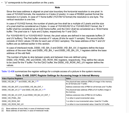
    In this case in interlaced mode the even field should have only white lines and the odd field should have only black lines. But this is not the case. I have in both odd and even field consecutive white and black lines. So odd and even field take consecutively the lines from the frame buffer which is not correct. Both fields should take every second line from the framebuffer. I see some registers in the trm which define such behavior - DSS0_VID_ROW_INC and DSS0_VID_ROW_INC_UV. I had in them value 0x1. I set in both registers value 0x2 but the picture did not change. Obviously this is not taken into account for some reason.

    If you have some more information about this problem let me know.

  • Ok, I think it uses the video lite pipeline and I have to think how to set it up for the interlaced mode.

  • Hi,
    I don't think VIDL (VideoLite) pipeline is involved. Check out the following:

    Only registers you may need to modify are DSS_VID_xxx and not the DSS_VIDL1_xxx registers.

  • Hi Divyansh,

    I managed to make interlaced mode working with this patch which is in development state and needs to be reworked:

    diff --git a/drivers/gpu/drm/drm_probe_helper.c b/drivers/gpu/drm/drm_probe_helper.c
    index c90afb5d0898..aa2921277cbe 100644
    --- a/drivers/gpu/drm/drm_probe_helper.c
    +++ b/drivers/gpu/drm/drm_probe_helper.c
    @@ -71,8 +71,10 @@ drm_mode_validate_flag(const struct drm_display_mode *mode,
                           int flags)
     {
            if ((mode->flags & DRM_MODE_FLAG_INTERLACE) &&
    -           !(flags & DRM_MODE_FLAG_INTERLACE))
    +           !(flags & DRM_MODE_FLAG_INTERLACE)) {
    +               pr_warn("Interlace not supported, mode flags 0x%x, flags 0x%x\n", mode->flags, flags);
                    return MODE_NO_INTERLACE;
    +       }
     
            if ((mode->flags & DRM_MODE_FLAG_DBLSCAN) &&
                !(flags & DRM_MODE_FLAG_DBLSCAN))
    diff --git a/drivers/gpu/drm/tidss/tidss_crtc.c b/drivers/gpu/drm/tidss/tidss_crtc.c
    index 14691f346f11..dc48dcddc397 100644
    --- a/drivers/gpu/drm/tidss/tidss_crtc.c
    +++ b/drivers/gpu/drm/tidss/tidss_crtc.c
    @@ -109,11 +109,12 @@ static int tidss_crtc_atomic_check(struct drm_crtc *crtc,
     
            ok = dispc_vp_mode_valid(dispc, hw_videoport, mode);
            if (ok != MODE_OK) {
    -               dev_dbg(ddev->dev, "%s: bad mode: %ux%u pclk %u kHz\n",
    +               dev_warn(ddev->dev, "%s: bad mode: %ux%u pclk %u kHz\n",
                            __func__, mode->hdisplay, mode->vdisplay, mode->clock);
                    return -EINVAL;
            }
     
    +       //drm_mode_set_crtcinfo(&crtc_state->adjusted_mode, mode->flags & DRM_MODE_FLAG_INTERLACE ? CRTC_INTERLACE_HALVE_V : 0);
            drm_mode_set_crtcinfo(&crtc_state->adjusted_mode, 0);
            return dispc_vp_bus_check(dispc, hw_videoport, crtc_state);
     }
    @@ -393,7 +394,7 @@ enum drm_mode_status tidss_crtc_mode_valid(struct drm_crtc *crtc,
            struct drm_device *ddev = crtc->dev;
            struct tidss_device *tidss = to_tidss(ddev);
     
    -       return dispc_vp_mode_valid(tidss->dispc, tcrtc->hw_videoport, mode);
    +       return dispc_vp_mode_valid(tidss->dispc, tcrtc->hw_videoport, mode);
     }
     
     static const struct drm_crtc_helper_funcs tidss_crtc_helper_funcs = {
    diff --git a/drivers/gpu/drm/tidss/tidss_dispc.c b/drivers/gpu/drm/tidss/tidss_dispc.c
    index 317ff8f420a6..8211da90e7b5 100644
    --- a/drivers/gpu/drm/tidss/tidss_dispc.c
    +++ b/drivers/gpu/drm/tidss/tidss_dispc.c
    @@ -1399,8 +1399,10 @@ enum drm_mode_status dispc_vp_mode_valid(struct dispc_device *dispc,
                    return MODE_BAD;
     
            /* TODO: add interlace support */
    -       if (mode->flags & DRM_MODE_FLAG_INTERLACE)
    -               return MODE_NO_INTERLACE;
    +       if (mode->flags & DRM_MODE_FLAG_INTERLACE) {
    +               //dev_warn(dispc->dev, "%s: No interlace support in tidss but continue as we need it\n", __func__);
    +               //return MODE_NO_INTERLACE;
    +       }
     
            /*
             * Enforce the output width is divisible by 2. Actually this
    @@ -2294,10 +2296,11 @@ void dispc_plane_setup(struct dispc_device *dispc, u32 hw_plane,
     
            dispc_plane_set_pixel_format(dispc, hw_plane, fourcc);
     
    +       //dev_warn(dispc->dev, "hw_plane=%d, lite=%d, dma_addr=0x%llx, fourcc=0x%x, fb_width %d, cpp %d, yinc %d, xinc %d\n", hw_plane, lite, dma_addr, fourcc, fb_width, cpp, scale.yinc, scale.xinc);
            dispc_vid_write(dispc, hw_plane, DISPC_VID_BA_0, dma_addr & 0xffffffff);
            dispc_vid_write(dispc, hw_plane, DISPC_VID_BA_EXT_0, (u64)dma_addr >> 32);
    -       dispc_vid_write(dispc, hw_plane, DISPC_VID_BA_1, dma_addr & 0xffffffff);
    -       dispc_vid_write(dispc, hw_plane, DISPC_VID_BA_EXT_1, (u64)dma_addr >> 32);
    +       dispc_vid_write(dispc, hw_plane, DISPC_VID_BA_1, (dma_addr + fb_width*cpp) & 0xffffffff);
    +       dispc_vid_write(dispc, hw_plane, DISPC_VID_BA_EXT_1, (u64)(dma_addr + fb_width*cpp) >> 32);
     
            dispc_vid_write(dispc, hw_plane, DISPC_VID_PICTURE_SIZE,
                            (scale.in_w - 1) | ((scale.in_h - 1) << 16));
    @@ -2310,10 +2313,13 @@ void dispc_plane_setup(struct dispc_device *dispc, u32 hw_plane,
                    dispc_vid_write(dispc, hw_plane, DISPC_VID_PIXEL_INC,
                                    pixinc(scale.xinc, cpp));
     
    +       //dispc_vid_write(dispc, hw_plane, DISPC_VID_ROW_INC,
    +       //              pixinc(1 + (scale.yinc * fb_width -
    +       //                          scale.xinc * scale.in_w),
    +       //                     cpp));
    +       //dev_warn(dispc->dev, "inc one row with %d\n", pixinc(fb_width+1, cpp));
            dispc_vid_write(dispc, hw_plane, DISPC_VID_ROW_INC,
    -                       pixinc(1 + (scale.yinc * fb_width -
    -                                   scale.xinc * scale.in_w),
    -                              cpp));
    +                       pixinc(fb_width+1, cpp));
     
            if (state->fb->format->num_planes == 2) {
                    u16 cpp_uv = state->fb->format->cpp[1];
    diff --git a/drivers/gpu/drm/tidss/tidss_encoder.c b/drivers/gpu/drm/tidss/tidss_encoder.c
    index 17a86bed8054..4af343d4f16a 100644
    --- a/drivers/gpu/drm/tidss/tidss_encoder.c
    +++ b/drivers/gpu/drm/tidss/tidss_encoder.c
    @@ -116,6 +116,8 @@ int tidss_encoder_create(struct tidss_device *tidss,
                    return PTR_ERR(connector);
            }
     
    +       connector->interlace_allowed = true;
    +
            ret = drm_connector_attach_encoder(connector, enc);
            if (ret) {
                    dev_err(tidss->dev, "attaching encoder to connector failed\n");
    diff --git a/drivers/gpu/drm/tidss/tidss_kms.c b/drivers/gpu/drm/tidss/tidss_kms.c
    index a0e494c806a9..831f8165cded 100644
    --- a/drivers/gpu/drm/tidss/tidss_kms.c
    +++ b/drivers/gpu/drm/tidss/tidss_kms.c
    @@ -175,6 +175,8 @@ static int tidss_dispc_modeset_init(struct tidss_device *tidss)
                            }
                    }
     
    +               dev_warn(dev, "Bridge interlace_allowed %d\n", bridge->interlace_allowed);
    +               bridge->interlace_allowed = true;
                    pipes[num_pipes].hw_videoport = i;
                    pipes[num_pipes].bridge = bridge;
                    pipes[num_pipes].enc_type = enc_type;

    I am going to make this patch better as some things are just made to prove interlaced mode is possible to set. With this patch interlaced mode is hard coded and scaling is probably broken.

    Now the picture from kmstest looks like this:

    I can say for sure VIDL1 is used as I put debugs and also I can see the change in the VIDL1_ROW_INC register:

    rwmem 0x3020221c
    0x3020221c (+0x0) = 0x00000b41

    I have some trouble with the first 4 pixels of the 1st line in the even field. The 4 pixels change constantly for some reason. The behavior of this pixels is really strange as some time these pixels are OK but the 4 pixels of the 1st line of the odd field are wrong. I still do not know what is the root cause of this behavior and why it is different every time.

  • When I have some better patch I will put it here again.

  • Hi ,

    Is it possible to define a seperate plane for the video output?

    If yes, how would I go about creating a plane for the active video data in my previous post?

    Ideally I would output to a seperate plane using kmssink, and have the rest automatically set to black.

    Thanks,

    Bas Vermeulen

  • Hi ,

    Yes, this would fit. Is there a way to configure the parameters for plane 41 from the device tree or the simple-panel?

    Basically, I would like to change width/height and specify an x and y for the plane to start. Probably the same for the zpos for both plane 31 and plane 41.

    I understand this can be done using modetest, but I would prefer to configure it statically in the device tree or driver.

    Regards,

    Bas Vermeulen

  • Hi,
    modetest is an example application on using the DRM framework to use z order and alpha blending. It is highly recommended that you use DRM framework for such configuration.

    Even then, if you need to use dt/driver, please try playing around with these registers:
    OVR1_ATTRIBUTES_0
    OVR1_ATTRIBUTES_1
    VID_PICTURE_SIZE
    VIDL1_PICTURE_SIZE

  • Hi  ,

    I am using gstreamer with the kmssink plugin to output to the display (which is working now).

    I have set the rendering-rectangle parameter of the kmssink plugin (x = 97, y = 8, width = 528, height = 410). This kinda works (I see the video displayed in that area), but I see ghosting in the area below that.

    (This is a picture of the screen, I hope the ghosting is visible)

    Any idea what could cause this? It looks like some frames are repeated in the part not actively written.

    Regards,

    Bas Vermeulen

  • Not able to see/understand what you trying to show from the pic.

  • To remove any source of error that may be from the application code, can you please try running following 2 examples:

    kmscube --device=/dev/dri/card0
    kmstest --device=/dev/dri/card0 --flip

  • Sorry about that. The screen shows my video in the top part, with several lines in the bottom not being written. The top part of the video comes back in the part of the screen that is not actively written.

  • I'll get back to you tomorrow, when I'm in the office. I'm trying to show things through a camera, and it's not showing what I want it to show.

  • Here are the patches I made to support the interlace mode in our platform for kernel 6.6.58

    First the patches mentioned here are needed:

     [FAQ] AM62P: Enabling BT.656 mode in DSS 

    Then with the following 3 patches applied we have 720x487 interlaced mode working using BT.656 format.

    From bb613f8ae373ea94271a2f5004c455635de25b5e Mon Sep 17 00:00:00 2001
    From: Nikolay Nikolov <nikolay.nikolov@bench.com>
    Date: Wed, 18 Jun 2025 18:01:43 +0200
    Subject: Add interlaced support in tidss
    
    Signed-off-by: Nikolay Nikolov <nikolay.nikolov@bench.com>
    ---
     drivers/gpu/drm/tidss/tidss_crtc.c    |  2 +-
     drivers/gpu/drm/tidss/tidss_dispc.c   | 22 ++++++++++++++--------
     drivers/gpu/drm/tidss/tidss_encoder.c |  2 ++
     drivers/gpu/drm/tidss/tidss_kms.c     |  1 +
     drivers/gpu/drm/tidss/tidss_plane.c   |  3 +++
     5 files changed, 21 insertions(+), 9 deletions(-)
    
    diff --git a/drivers/gpu/drm/tidss/tidss_crtc.c b/drivers/gpu/drm/tidss/tidss_crtc.c
    index 14691f346f11..28c59ed9e220 100644
    --- a/drivers/gpu/drm/tidss/tidss_crtc.c
    +++ b/drivers/gpu/drm/tidss/tidss_crtc.c
    @@ -114,7 +114,7 @@ static int tidss_crtc_atomic_check(struct drm_crtc *crtc,
     		return -EINVAL;
     	}
     
    -	drm_mode_set_crtcinfo(&crtc_state->adjusted_mode, 0);
    +	drm_mode_set_crtcinfo(&crtc_state->adjusted_mode, mode->flags & DRM_MODE_FLAG_INTERLACE ? CRTC_INTERLACE_HALVE_V : 0);
     	return dispc_vp_bus_check(dispc, hw_videoport, crtc_state);
     }
     
    diff --git a/drivers/gpu/drm/tidss/tidss_dispc.c b/drivers/gpu/drm/tidss/tidss_dispc.c
    index 7ae680ca5d2b..303e07768bf7 100644
    --- a/drivers/gpu/drm/tidss/tidss_dispc.c
    +++ b/drivers/gpu/drm/tidss/tidss_dispc.c
    @@ -26,6 +26,7 @@
     #include <drm/drm_framebuffer.h>
     #include <drm/drm_gem_dma_helper.h>
     #include <drm/drm_panel.h>
    +#include <drm/drm_atomic.h>
     
     #include "tidss_crtc.h"
     #include "tidss_dispc.h"
    @@ -1398,10 +1399,6 @@ enum drm_mode_status dispc_vp_mode_valid(struct dispc_device *dispc,
     	if (mode->vdisplay > 4096)
     		return MODE_BAD;
     
    -	/* TODO: add interlace support */
    -	if (mode->flags & DRM_MODE_FLAG_INTERLACE)
    -		return MODE_NO_INTERLACE;
    -
     	/*
     	 * Enforce the output width is divisible by 2. Actually this
     	 * is only needed in following cases:
    @@ -2289,18 +2286,27 @@ void dispc_plane_setup(struct dispc_device *dispc, u32 hw_plane,
     	u32 fb_width = state->fb->pitches[0] / cpp;
     	dma_addr_t dma_addr = dispc_plane_state_dma_addr(state);
     	struct dispc_scaling_params scale;
    +	struct drm_crtc_state *crtc_state = NULL;
    +	bool ilace = false;
     
     	dispc_vid_calc_scaling(dispc, state, &scale, lite);
     
     	dispc_plane_set_pixel_format(dispc, hw_plane, fourcc);
     
    +	if(state->crtc && state->state) {
    +		crtc_state = drm_atomic_get_new_crtc_state(state->state, state->crtc);
    +		if(crtc_state && (crtc_state->adjusted_mode.flags & DRM_MODE_FLAG_INTERLACE)) {
    +			ilace = true;
    +		}
    +	}
    +
     	dispc_vid_write(dispc, hw_plane, DISPC_VID_BA_0, dma_addr & 0xffffffff);
     	dispc_vid_write(dispc, hw_plane, DISPC_VID_BA_EXT_0, (u64)dma_addr >> 32);
    -	dispc_vid_write(dispc, hw_plane, DISPC_VID_BA_1, dma_addr & 0xffffffff);
    -	dispc_vid_write(dispc, hw_plane, DISPC_VID_BA_EXT_1, (u64)dma_addr >> 32);
    +	dispc_vid_write(dispc, hw_plane, DISPC_VID_BA_1, (dma_addr + (ilace ? fb_width*cpp : 0)) & 0xffffffff);
    +	dispc_vid_write(dispc, hw_plane, DISPC_VID_BA_EXT_1, (u64)(dma_addr + (ilace ? fb_width*cpp : 0)) >> 32);
     
     	dispc_vid_write(dispc, hw_plane, DISPC_VID_PICTURE_SIZE,
    -			(scale.in_w - 1) | ((scale.in_h - 1) << 16));
    +			(scale.in_w - 1) | ((scale.in_h/(ilace ? 2 : 1) - 1) << 16));
     
     	/* For YUV422 format we use the macropixel size for pixel inc */
     	if (fourcc == DRM_FORMAT_YUYV || fourcc == DRM_FORMAT_UYVY)
    @@ -2312,7 +2318,7 @@ void dispc_plane_setup(struct dispc_device *dispc, u32 hw_plane,
     
     	dispc_vid_write(dispc, hw_plane, DISPC_VID_ROW_INC,
     			pixinc(1 + (scale.yinc * fb_width -
    -				    scale.xinc * scale.in_w),
    +				    scale.xinc * scale.in_w) + (ilace ? fb_width : 0),
     			       cpp));
     
     	if (state->fb->format->num_planes == 2) {
    diff --git a/drivers/gpu/drm/tidss/tidss_encoder.c b/drivers/gpu/drm/tidss/tidss_encoder.c
    index 17a86bed8054..4af343d4f16a 100644
    --- a/drivers/gpu/drm/tidss/tidss_encoder.c
    +++ b/drivers/gpu/drm/tidss/tidss_encoder.c
    @@ -116,6 +116,8 @@ int tidss_encoder_create(struct tidss_device *tidss,
     		return PTR_ERR(connector);
     	}
     
    +	connector->interlace_allowed = true;
    +
     	ret = drm_connector_attach_encoder(connector, enc);
     	if (ret) {
     		dev_err(tidss->dev, "attaching encoder to connector failed\n");
    diff --git a/drivers/gpu/drm/tidss/tidss_kms.c b/drivers/gpu/drm/tidss/tidss_kms.c
    index a0e494c806a9..0c8b1317322b 100644
    --- a/drivers/gpu/drm/tidss/tidss_kms.c
    +++ b/drivers/gpu/drm/tidss/tidss_kms.c
    @@ -175,6 +175,7 @@ static int tidss_dispc_modeset_init(struct tidss_device *tidss)
     			}
     		}
     
    +		bridge->interlace_allowed = true;
     		pipes[num_pipes].hw_videoport = i;
     		pipes[num_pipes].bridge = bridge;
     		pipes[num_pipes].enc_type = enc_type;
    diff --git a/drivers/gpu/drm/tidss/tidss_plane.c b/drivers/gpu/drm/tidss/tidss_plane.c
    index 084c7ef84893..a006d27ffadf 100644
    --- a/drivers/gpu/drm/tidss/tidss_plane.c
    +++ b/drivers/gpu/drm/tidss/tidss_plane.c
    @@ -132,6 +132,9 @@ static void tidss_plane_atomic_update(struct drm_plane *plane,
     
     	hw_videoport = to_tidss_crtc(new_state->crtc)->hw_videoport;
     
    +	/* Not sure how safe this is. Hopefully it does not harm to update the pointer in the state structure with the valid one */
    +	if (new_state->state == NULL)
    +		new_state->state = state;
     	dispc_plane_setup(tidss->dispc, tplane->hw_plane_id, new_state, hw_videoport);
     }
     
    -- 
    2.34.1
    

    rom 9501aed598a5590bfb059c640b6bdf9b42f9915c Mon Sep 17 00:00:00 2001
    From: Nikolay Nikolov <nikolay.nikolov@bench.com>
    Date: Fri, 4 Jul 2025 13:52:03 +0200
    Subject: Set registers for BT656 487i mode
    
    Signed-off-by: Nikolay Nikolov <nikolay.nikolov@bench.com>
    ---
     drivers/gpu/drm/tidss/tidss_dispc.c | 76 +++++++++++++++++++++--------
     1 file changed, 55 insertions(+), 21 deletions(-)
    
    diff --git a/drivers/gpu/drm/tidss/tidss_dispc.c b/drivers/gpu/drm/tidss/tidss_dispc.c
    index de90374a49c0..30697124fa65 100644
    --- a/drivers/gpu/drm/tidss/tidss_dispc.c
    +++ b/drivers/gpu/drm/tidss/tidss_dispc.c
    @@ -1200,7 +1200,6 @@ void dispc_vp_enable(struct dispc_device *dispc, u32 hw_videoport,
     	const struct tidss_crtc_state *tstate = to_tidss_crtc_state(state);
     	bool align, onoff, rf, ieo, ipc, ihs, ivs;
     	const struct dispc_bus_format *fmt;
    -	u32 hsw, hfp, hbp, vsw, vfp, vbp;
     
     	fmt = dispc_vp_find_bus_fmt(dispc, hw_videoport, tstate->bus_format,
     				    tstate->bus_flags);
    @@ -1210,32 +1209,51 @@ void dispc_vp_enable(struct dispc_device *dispc, u32 hw_videoport,
     
     	dispc_set_num_datalines(dispc, hw_videoport, fmt->data_width);
     
    -	hfp = mode->hsync_start - mode->hdisplay;
    -	hsw = mode->hsync_end - mode->hsync_start;
    -	hbp = mode->htotal - mode->hsync_end;
    +	if (dispc->tidss->bt656_enabled) {
    +		u32 vfb1e, vfb2e, vfb1o, fvb2o, hb;
     
    -	vfp = mode->vsync_start - mode->vdisplay;
    -	vsw = mode->vsync_end - mode->vsync_start;
    -	vbp = mode->vtotal - mode->vsync_end;
    +		vfb1e = mode->hsync_start - mode->hdisplay;
    +		vfb2e = mode->hsync_end - mode->hsync_start;
    +		vfb1o = mode->vsync_start - mode->vdisplay;
    +		fvb2o = mode->vsync_end - mode->vsync_start;
    +		hb = ((mode->htotal - mode->hdisplay) - 4)*2 - 1;
     
    -	if (dispc->tidss->bt656_enabled) {
     		dispc_vp_write(dispc, hw_videoport, DISPC_VP_TIMING_H,
    -				FLD_VAL(((hsw & 0xFF) - 1), 7, 0) |
    -				FLD_VAL(hfp - 1, 19, 8) |
    -				FLD_VAL(hbp - 1, 31, 20));
    +				FLD_VAL(hb & 0x00FF, 7, 0) |
    +				FLD_VAL(vfb1e, 19, 8) |
    +				FLD_VAL(vfb2e, 31, 20));
    +
    +		dispc_vp_write(dispc, hw_videoport, DISPC_VP_TIMING_V,
    +				FLD_VAL((hb >> 8), 3, 0) |
    +				FLD_VAL(vfb1o, 19, 8) |
    +				FLD_VAL(fvb2o, 31, 20));
    +		/*
    +		dispc_vp_write(dispc, hw_videoport, DISPC_VP_TIMING_H,
    +				FLD_VAL(0x0B, 7, 0) |
    +				FLD_VAL(0x01, 19, 8) |
    +				FLD_VAL(0x0F, 31, 20));
    +
    +		dispc_vp_write(dispc, hw_videoport, DISPC_VP_TIMING_V,
    +				FLD_VAL(0x01, 3, 0) |
    +				FLD_VAL(0x02, 19, 8) |
    +				FLD_VAL(0x10, 31, 20));
    +		*/
     	} else {
    +		u32 hsw, hfp, hbp, vsw, vfp, vbp;
    +
    +		hfp = mode->hsync_start - mode->hdisplay;
    +		hsw = mode->hsync_end - mode->hsync_start;
    +		hbp = mode->htotal - mode->hsync_end;
    +
    +		vfp = mode->vsync_start - mode->vdisplay;
    +		vsw = mode->vsync_end - mode->vsync_start;
    +		vbp = mode->vtotal - mode->vsync_end;
    +
     		dispc_vp_write(dispc, hw_videoport, DISPC_VP_TIMING_H,
     				FLD_VAL(hsw - 1, 7, 0) |
     				FLD_VAL(hfp - 1, 19, 8) |
     				FLD_VAL(hbp - 1, 31, 20));
    -	}
     
    -	if (dispc->tidss->bt656_enabled) {
    -		dispc_vp_write(dispc, hw_videoport, DISPC_VP_TIMING_V,
    -				FLD_VAL(((hsw) >> 8), 3, 0) |
    -				FLD_VAL(vfp, 19, 8) |
    -				FLD_VAL(vbp, 31, 20));
    -	} else {
     		dispc_vp_write(dispc, hw_videoport, DISPC_VP_TIMING_V,
     				FLD_VAL(vsw - 1, 7, 0) |
     				FLD_VAL(vfp, 19, 8) |
    @@ -1271,9 +1289,25 @@ void dispc_vp_enable(struct dispc_device *dispc, u32 hw_videoport,
     		       FLD_VAL(ihs, 13, 13) |
     		       FLD_VAL(ivs, 12, 12));
     
    -	dispc_vp_write(dispc, hw_videoport, DISPC_VP_SIZE_SCREEN,
    -		       FLD_VAL(mode->hdisplay - 1, 11, 0) |
    -		       FLD_VAL(mode->vdisplay - 1, 27, 16));
    +	if (dispc->tidss->bt656_enabled) {
    +		u16 vdisplay = mode->vdisplay / 2;
    +		u8 delta_lpp = 0x00;
    +		if ((mode->vdisplay & 0x01) == 0x01) {
    +			delta_lpp = 0x02;		//Odd size is even size minus 1
    +		} else {
    +			vdisplay -= 1;
    +		}
    +		dispc_vp_write(dispc, hw_videoport, DISPC_VP_SIZE_SCREEN,
    +				FLD_VAL(mode->hdisplay - 1, 11, 0) | FLD_VAL(delta_lpp, 15, 14) |
    +				FLD_VAL(vdisplay, 27, 16));
    +		if (mode->flags & DRM_MODE_FLAG_INTERLACE) {
    +			VP_REG_FLD_MOD(dispc, hw_videoport, DISPC_VP_CONFIG, 1, 22, 22);
    +		}
    +	} else {
    +		dispc_vp_write(dispc, hw_videoport, DISPC_VP_SIZE_SCREEN,
    +				FLD_VAL(mode->hdisplay - 1, 11, 0) |
    +				FLD_VAL(mode->vdisplay - 1, 27, 16));
    +	}
     
     	VP_REG_FLD_MOD(dispc, hw_videoport, DISPC_VP_CONTROL, 1, 0, 0);
     }
    -- 
    2.34.1

    From c04afa5e18b8a82bf950d4008ad09188ccb3c127 Mon Sep 17 00:00:00 2001
    From: Nikolay Nikolov <nikolay.nikolov@bench.com>
    Date: Mon, 14 Jul 2025 10:24:51 +0200
    Subject: Set BT656 720x487i mode line
    
    Signed-off-by: Nikolay Nikolov <nikolay.nikolov@bench.com>
    ---
     .../boot/dts/ti/k3-am62a7-4kcam-protoa.dts    |  2 +-
     drivers/gpu/drm/panel/panel-simple.c          | 32 +++++++++----------
     2 files changed, 17 insertions(+), 17 deletions(-)
    
    diff --git a/arch/arm64/boot/dts/ti/k3-am62a7-4kcam-protoa.dts b/arch/arm64/boot/dts/ti/k3-am62a7-4kcam-protoa.dts
    index 5b99978093df..93277d0a2197 100644
    --- a/arch/arm64/boot/dts/ti/k3-am62a7-4kcam-protoa.dts
    +++ b/arch/arm64/boot/dts/ti/k3-am62a7-4kcam-protoa.dts
    @@ -138,7 +138,7 @@ dma_buf_phys {
     	};
     
     	panel {
    -		compatible = "dummy,bt656-480p";
    +		compatible = "dummy,bt656-487i";
     
     		status = "okay";
     
    diff --git a/drivers/gpu/drm/panel/panel-simple.c b/drivers/gpu/drm/panel/panel-simple.c
    index cd85069509ba..9d946e542782 100644
    --- a/drivers/gpu/drm/panel/panel-simple.c
    +++ b/drivers/gpu/drm/panel/panel-simple.c
    @@ -1352,21 +1352,21 @@ static const struct panel_desc cdtech_s043wq26h_ct7 = {
     };
     
     /* S070PWS19HP-FC21 2017/04/22 */
    -static const struct drm_display_mode bt656_480p_mode = {
    -	.clock = 63125,
    +static const struct drm_display_mode bt656_487i_mode = {
    +	.clock = 27000,
     	.hdisplay = 720,
    -	.hsync_start = 720 + 20,
    -	.hsync_end = 720 + 20 + 552,
    -	.htotal = 720 + 20 + 3 + 552,
    -	.vdisplay = 480,
    -	.vsync_start = 480 + 38,
    -	.vsync_end = 480 + 38,
    -	.vtotal = 480 + 38 + 6,
    -	.flags = DRM_MODE_FLAG_NHSYNC | DRM_MODE_FLAG_NVSYNC,
    -};
    -
    -static const struct panel_desc bt656_480p = {
    -	.modes = &bt656_480p_mode,
    +	.hsync_start = 720 + 1,
    +	.hsync_end = 720 + 1 + 15,
    +	.htotal = 720 + 1 + 15 + 122,
    +	.vdisplay = 487,
    +	.vsync_start = 487 + 2,
    +	.vsync_end = 487 + 2 + 16,
    +	.vtotal = 487 + 2 + 16 + 20,
    +	.flags = DRM_MODE_FLAG_NHSYNC | DRM_MODE_FLAG_NVSYNC | DRM_MODE_FLAG_INTERLACE,
    +};
    +
    +static const struct panel_desc bt656_487i = {
    +	.modes = &bt656_487i_mode,
     	.num_modes = 1,
     	.bpc = 8,
     	.size = {
    @@ -4387,8 +4387,8 @@ static const struct of_device_id platform_of_match[] = {
     		.compatible = "cdtech,s070pws19hp-fc21",
     		.data = &cdtech_s070pws19hp_fc21,
     	}, {
    -		.compatible = "dummy,bt656-480p",
    -		.data = &bt656_480p,
    +		.compatible = "dummy,bt656-487i",
    +		.data = &bt656_487i,
     	}, {
     		.compatible = "cdtech,s070swv29hg-dc44",
     		.data = &cdtech_s070swv29hg_dc44,
    -- 
    2.34.1

       could you please review the patches and let me know if something is wrong, something else is needed or whatever else.

    Thanks and Regards,
    Nikolay Nikolov 

  • Hi Nikolay,
    Thanks for sharing the patches. Does it work completely fine on your side? Did you run kmstest --flip on your end? Seems kmstest probably has inbuilt support for interlaced mode, and you won't need to create separate FBs for the same.

  • kmstest --flip gives me the following output:

      Crtc 0/@38: 720x487i@119.88 27.000 720/1/15/122/- 487/2/16/20/- 120 (119.88) 0x1a 0x48
      Plane 0/@31: 0,0-720x487
        Fb 50 720x487-XR24
    press enter to exit
    Connector 0: fps 59.90, slowest 17.93 ms
    Connector 0: fps 59.94, slowest 16.82 ms
    Connector 0: fps 59.94, slowest 16.81 ms
    Connector 0: fps 59.94, slowest 16.79 ms
    Connector 0: fps 59.94, slowest 16.79 ms
    Connector 0: fps 59.94, slowest 16.82 ms
    Connector 0: fps 59.94, slowest 16.81 ms
    Connector 0: fps 59.94, slowest 16.78 ms
    Connector 0: fps 59.94, slowest 16.80 ms
    Connector 0: fps 59.94, slowest 16.78 ms
    Connector 0: fps 59.94, slowest 16.78 ms
    Connector 0: fps 59.94, slowest 16.79 ms
    Connector 0: fps 59.94, slowest 16.80 ms
    Connector 0: fps 59.94, slowest 16.80 ms

    I see a running bar going from left to right with the colors white, red, white, green, white, blue, white, light gray, white, gray, white, dark gray (from top to bottom).

    We are still seeing some problems with color swapping for some of our video output (full screen works fine, but when I add a videobox around it with gstreamer red and blue are swapped).

    We're still working on that last one. If you have any idea of what might be causing this, hints are welcomed ;)

    Regards,

    Bas Vermeulen

  • Thanks Bas. As of now, not sure what may be causing this, will share if something pops up. To confirm, you do not see the 'ghosting effect' with kmstest?

  • I see a ghosting effect if I run kmstest with a resolution below the actual resolution.

      Crtc 0/@38: 720x487i@119.88 27.000 720/1/15/122/- 487/2/16/20/- 120 (119.88) 0x1a 0x48
      Plane 0/@31: 0,10-720x400
        Fb 49 720x400-XR24
    press enter to exit
    Connector 0: fps 60.43, slowest 16.79 ms
    Connector 0: fps 59.94, slowest 16.73 ms
    Connector 0: fps 59.94, slowest 16.78 ms
    Connector 0: fps 59.94, slowest 16.78 ms
    Connector 0: fps 59.94, slowest 16.74 ms
    Connector 0: fps 59.94, slowest 16.82 ms
    Connector 0: fps 59.94, slowest 16.75 ms
    Connector 0: fps 59.94, slowest 16.93 ms

    With this, I see the color bar running left to right across the screen, with corruption in the screen where I'm not actively writing.

    I'm just not sure if this is normal or not.

  • Not sure if I understand completely. I believe you are using some sort of serializer/oscilloscope to see the frames and not an actual panel. Is this assumption correct? Active area of the screen is the region where you would actually visually see the data on a real panel and all the artefacts beyond active region won't be visible. My guess is you are seeing data beyond active region because you are not using display of exactly that resolution but something that is emulating display of larger resolution.
    Please correct my understanding of your setup wherever wrong.

  • I am using a display (720x487 interlaced). The kmstest call above configures a framebuffer on that display with a size smaller than the actual display size (starts at line 10, ends at line 410, with 720 width for each line).

  • Hi Divyansh,

    We have the problem Bas explained already and we are working on it. Also in this thread:

     RE: AM68A: DSS configuration for Bt656 interlaced output 

    Frank reported he has iinterlace mode working as well.

  • I'm running into some more problems where I don't know the cause:

    When using a stream from camera (4K -> multiscale to full hd -> multiscale to 720x486) using gstreamer, the picture isn't fluid on the camera. When I use a multiscaler in addition to get the output on screen that we need, things get even slower (.5 second jumps in the timer I have running on a phone that I take a video of).

    I've had gst_tracer running, and that gives me a nice 30 fps with a 100 ms latency from end to end.

    I've also noticed that I can't bring up a pipeline with HEVC encoding and kmssink at the same time, without running into a CPU bottleneck. Not sure what that is about.

  • Hi,

    in Nikolay's patch set you should also pay attention to the  DSS0_OVR_ATTRIBUTES2_x register. Especially SIZEY. It should be the size of the filed output - half the framebuffer (dispc_j721e_ovr_set_plane). Also the scaling setup (in dispc_plane_setup) should be half the size. This have been eliminated the corruption effect when not using the native display output size for me.

    With regards,

    Frank

  • Thanks for the hint Frank !

    I already knew there is some size which I forgot to update according to the interlace mode. In our platform is little bit different and the size is in different register. As it is written in the trm as MEMSIZEY in DSS0_PICTURE_SIZE register I thought it is for the memory of the whole image. But obviously it is not and has to be updated
    I updated my patches in the post above.

    Regards,
    Nikolay

  • Thanks Frank!
    Nikolay, does this help you with your existing issue?

  • We still have some troubles with the colors and picture when scaling down to smaller size.

  • Hi Divyansh,

    Please check this thread:

     AM62A7-Q1: tiovxmultiscaler causes color corruption

    Looks like the problem we have is caused by the tiovxmultiscaler gstreamer element.

  • That thread has been assigned to the concerned expert. Please await their response.