This thread has been locked.

If you have a related question, please click the "Ask a related question" button in the top right corner. The newly created question will be automatically linked to this question.

How do I setup a PCA9547 muxed i2c on by board file?

Other Parts Discussed in Thread: OMAPL138

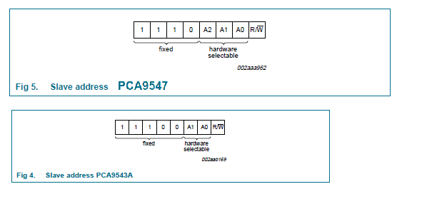
I have a board based on a da850 evm (omapl138). It has a PCA9547 connected to the omap. There is a device on channel 7 that has a driver available (call it FOO). How can I:

1. Instantiate the pca9547 driver? I've tried using the I2C_BOARD_INFO()/i2c_register_board_info() method.

2. Add the FOO device to channel 7 of the mux?

There is a pcs954x driver. However, I don;t know how to access the device/adapter/client it instantiates. I feel there must be an easier way. Also, the reason I'm trying us the drivers from by board file is that there will be userspace programs that will need to access the muxed devices. Thanks for any help!

Eric

  • Additional info:

    The MUX GPIO driver will not work with this chip as the chip is a mux and not a switch (the GPIO MUX driver only supports switches at this time).

    If I use the i2c.davinci driver as a platform device, instead of the i2c.gpio driver, timeouts occur.

    The linux distribution is from the linux-davinci git repo, the same as used by TI PSP3.22.00.06.
    I have enabled the PCA954x MUX driver.

    The board is configured without a UI expander. Instead, it has a PCA9547BS (8 channel mux) on the main board using address 0x73.

    My .config I2C options are:
    CONFIG_I2C_BOARDINFO=y
    CONFIG_I2C_CHARDEV=y
    CONFIG_I2C_COMPAT=y
    CONFIG_I2C_DAVINCI=y
    CONFIG_I2C_DEBUG_ALGO=y
    CONFIG_I2C_DEBUG_BUS=y
    CONFIG_I2C_DEBUG_CORE=y
    CONFIG_I2C_HELPER_AUTO=y
    CONFIG_I2C_INIT_USB_HUB=y
    CONFIG_I2C_MUX_PCA954x=y
    CONFIG_I2C_MUX=y
    CONFIG_I2C=y

    These options cause a timeout/bus recover.
    I've also tried CONFIG_I2C_GPIO and CONFIG_I2C_MUX_GPIO. No timeouts, but the PCA954X driver returns a -16 error status (-EBUSY) while trying to enumerate the virtual adapters.

  • Hi Eric,

    You mentioned that the slave address is 0x73; So the A0 and A1 input lines are pulled high and A2 is grounded ?

    As per your hardware, how are these lines (A0,A1,A2) connected? 

    If all these lines are grounded, the address should be framed as 0b01110000 --> 0x70 ;If all are pulled high, the address will be 0x77.

    If 7th channel needs to be accessed, then the control register should also be configured appropriately.

    What are the slave device connected to 7th channel. Whether the modification for pca9547 is done in the board file with reference to pca9543?

    Please share your board file and the bootlogs with error messages.


    Regards,

    Shankari

    -------------------------------------------------------------------------------------------------------

    Please click the Verify Answer button on this post if it answers your question.
    --------------------------------------------------------------------------------------------------------