This thread has been locked.

If you have a related question, please click the "Ask a related question" button in the top right corner. The newly created question will be automatically linked to this question.

TMS320C6415: Intermittent failure to complete boot process on power up

Part Number: TMS320C6415

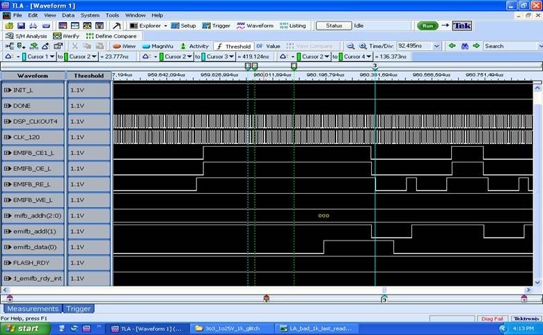
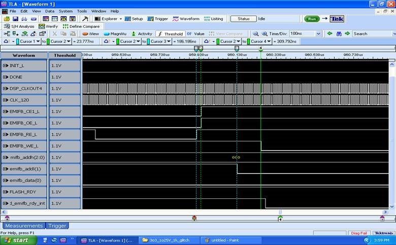
Hello, I am using TMS320C6415 and have an intermittent issue where the device hangs during power up and does not complete the boot process.  The issue occurs at all temperatures.  I have attempted to attach an emulator to read the EMIFB and EDMA registers but I am unable to connect to the device when it is in a failed state.  The device bootmode is set to EMIFB 8-bit ROM boot.  The EMIFB input clock is set to CPU/4 Clock rate.  The failure appears to happen either at the end of the 1K byte transfer from Flash using the internal boot loader, or somewhere in the middle of the second boot transfer from flash that is setup using the code that is contained in the first 1K bytes that is transferred using the internal boot loader.  The flash device is PC28F256M29EWLA.  Below are logic analyzer captures at the end of the 1K boot transfer for a passing and failing condition.  In a failing condition, the DSP device drives EMIFB_WE_L active.  This signal should not be active as the device is still in the process of reading boot code from the flash device.  The reset to the DSP device is being driven from an FPGA.  During power on the reset is held in the active state through a reset monitor, then after the FPGA configures it drives a reset pulse to the DSP that occurs 50 ms after power on reset, the reset pulse is about 800 us wide.  Any help on where to look or what would cause the DSP to intermittently drive EMIFB_WE_L active during the boot process would be greatly appreciated, thank you.

Passing condition at end of 1K byte boot transfer, secondary boot transfer starts:

Failing condition, EMIFB_WE_L drive low for unknown reason at end of 1K boot transfer, secondary boot transfer never starts:

  • Andrew,

    Some comments to see if I understand correctly, questions to get some clarification, and thoughts on debugging:

    Comments:

    C1. In both screen shots, it appears that when CE1 goes from 0 on the far left to 1 near the middle, that is the end of the 1K auto-transfer.
    C2a. In the passing case, CE1 appears to be high about 550ns, at which time it appears that the EMIFB timing has been optimized and new reads are starting; also D0 goes high at about the 400ns point after CE1 goes high.
    C2b. In the failing case, the time from CE1 / to A1 \ is only 186ns and the WE \ happens at 310ns from CE1 /.

    Questions:

    Q1. Which other CEx are you using? The fact that D0 and A1 are toggling without CE1 being low implies that the EMIFB is trying to drive another memory space.
    Q2. Or is there another bus master on EMIFB?
    Q3. How repeatable is the failure? On how many boards, out of how many never fail?

    Debugging:

    D1. If you raise or lower temperature or voltage, does it affect the repeatability of the failure?
    D2. Perhaps depending on Q3, it could help to put some pin-toggling into the 1KB initial boot code to see if anything valid starts to run, and how far into the code it gets. Toggling a GPIO might be best, or doing a dummy read could be enough to get a little observability inside the secondary boot operation.
    D3. Perhaps depending on Q3, you could have CCS connected and apply a reset from within CCS that will trigger a hardware re-boot.
    D4. Can you apply repeated resets from the FPGA and just observe the failure rate? It would be interesting to see if the failure rate is tied to being right after power-on or not. The PLL setting could be a factor, too.

    That will get us started. More tomorrow after your feedback.

    Regards,
    RandyP
  • Thank you Randy for the response and info.  Below are answers to your questions and comments:

    C1. In both screen shots, it appears that when CE1 goes from 0 on the far left to 1 near the middle, that is the end of the 1K auto-transfer.  That is correct, that is what we believe also.
    C2a. In the passing case, CE1 appears to be high about 550ns, at which time it appears that the EMIFB timing has been optimized and new reads are starting; also D0 goes high at about the 400ns point after CE1 goes high.  Exactly right, the code in the 1K initial boot sector has now optimized the Flash access timing for the second 16K boot transfer because it now knows which flash device it is talking to.
    C2b. In the failing case, the time from CE1 / to A1 \ is only 186ns and the WE \ happens at 310ns from CE1 /

    Q1. Which other CEx are you using? The fact that D0 and A1 are toggling without CE1 being low implies that the EMIFB is trying to drive another memory space.  All 4 EBIFB CEs are routed from the DSP to FPGA, the FPGA then routes to the appropriate devices on the EMIFB Bus.  CE0 is routed to a UART in FW, CE1 is routed to the boot flash, CE2 is routed to a different memory, CE3 is routed to a transceiver chip.
    Q2. Or is there another bus master on EMIFB?  No other masters on EMIFB, only the DSP
    Q3. How repeatable is the failure? On how many boards, out of how many never fail?  We currently have about 20 failing boards, the failure started occurring more frequently on boards assembled mid-late last year.  Roughly a 10-20% failure rate based on total # of boards.  The failure is intermittent on all boards, failure rate ranges from about 10%-50%. 

    D1. If you raise or lower temperature or voltage, does it affect the repeatability of the failure?  Different boards exhibit this failure at different temperatures, a majority of the boards fail at either a hot or cold temperature extreme.  A few boards fail at ambient and those are the boards we have been debugging with due to ease of probing signals and testing.
    D2. Perhaps depending on Q3, it could help to put some pin-toggling into the 1KB initial boot code to see if anything valid starts to run, and how far into the code it gets. Toggling a GPIO might be best, or doing a dummy read could be enough to get a little observability inside the secondary boot operation.  Haven't tried this yet, but yes good suggestion, will need to get someone from our SW group to modify the boot code which might take a few days.
    D3. Perhaps depending on Q3, you could have CCS connected and apply a reset from within CCS that will trigger a hardware re-boot.  Haven't tried this yet either.
    D4. Can you apply repeated resets from the FPGA and just observe the failure rate? It would be interesting to see if the failure rate is tied to being right after power-on or not. The PLL setting could be a factor, too.  The failure does occur if a board level reset is applied to the board several minutes after power up.  This board reset also triggers a reconfigure of the FPGA.  So it does not appear to be tied only to a power up condition.

    Thanks again for your info and suggestions, any further suggestions or info would be greatly appreciated.

  • Andrew,

    Are you using the C6415 or the C6415T? It might make a difference in emulation features.

    In particular, I am wondering about the availability of the hardware breakpoints. The C6415/T is a fairly old DSP so I do not remember if it had hardware breakpoints. I think it did, and that could be a big help for debugging this boot problem.

    FYI, there is a good Wiki article Debugging Boot Issues that has some good ideas to consider or at least check off your list.

    With CCS/JTAG connected, if a hardware breakpoint is available on the part that would be a good debug tool. You can set a hardware breakpoint at the beginning of L2 at 0x00000000 to stop the processor as soon as it is started after the 1KB initial bootload. If hardware breakpoints are not available or do not survive through the power cycle/reset process, then an alternative would be to jam a B $ instruction at address 0x00000000.

    Either way, if you can get the DSP to stop as soon as it has finished the copy, then you can use the CCS Memory Save command to copy the 1KB from L2 to a file, and then compare that file to a known good copy. From your failure rate estimates, you should be able to do this several times and manage to find out whether the 1KB varies ever. This will help draw a line between a successful or unsuccessful copy from Flash/FPGA. If it ever miscompares, then you know to look for incoming data differences.

    If the 1KB never varies, then the debugging will have to move later in the code, and that will require similar control (via hw breakpoints or B $) or observability (toggling a pin or dummy writing to EMIFB CE1).

    You will likely need the SW group to come in and work with you in the lab.

    Regards,
    RandyP

  • Hello Randy,

    The full PN of the device we are using is:  TMS32C6415EGLZA5E0.  Does this have HW breakpoints available?  The issue we had with the emulation pod is not having enough time to connect the pod after power up and before the boot error happened.  We tried adding a delay loop but still had issues.  Is there a way to have the emulation pod automatically connected at power up?  The emulation pod would need to be initialized and connected to the processor in order to use the B $ instruction or HW breakpoint correct?  I guess I am struggling to understand how the emulation pod would have enough time to connect to the target device before the 1KB boot transfer completes.  And I can't really add anything to the boot code we wrote because the 1KB transfer is under the HW control of the DSP if I understand correctly.

    Thank you for the link on Debugging Boot Issues, I tried it however and it said the page no longer exists.  Do you have an alternate link or other resources I could look at to help debugging this boot issue?

    Thank you for the info.

    Andrew Held

  • Andrew,

    The E2E editor likes inserting a bunch of extra stuff in front of the URL for the Wiki page, sometimes. I think I have it fixed now in the post above, but the URL is processors.wiki.ti.com/.../Debugging_Boot_Issues .

    The B $ should work no matter how long it takes to connect. The DSP will do the 1KB download then start running and hit the B $. It will stay there until you get the debugger connected and ready. That is assuming that the 1KB copy completes good or bad and starts running at 0. It will be the same effect as a hardware breakpoint.

    If hardware breakpoints are available, you can set one by right clicking on the line and selecting breakpoints. Since I do not have a C6415 to try it on, I cannot tell you exactly how. Which version of CCS are you using, and which JTAG pod?

    If you can get the failure to happen without a power cycle, it will be easier to get the emulator connected. With just a reset, you might not have any problem, but you will just have to play with the different combinations of disconnect & reset & reconnect, or there might be a runfree that logically disconnects without functionally disconnecting.

    Regards,
    RandyP