This thread has been locked.

If you have a related question, please click the "Ask a related question" button in the top right corner. The newly created question will be automatically linked to this question.

DRA744: MII & RMII driver

Part Number: DRA744
Other Parts Discussed in Thread: DRA714, DRA746

Hello

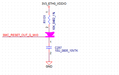
We use Micrel KSZ8081MNX to receive MII signal from DRA744 before, and it's working. We change component to another MPN,Micrel KSZ8081RNB, receiving RMII signal  now.

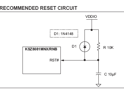
It's not working, is there new driver to update?KSZ8081MNX-RNB_DS00002202A.pdf

  • Hi,

    I may miss something, but I think of these steps:

    1. Check that you can read Micrel registers via MDIO

    2. Due to MII to RMII migration, check:

     - all RMII signal routing, kindly post a schematic diagram if possible

     - check that 50Mhz clock is not set generated in DRA744 (due to errata)

     - check GMII1_SEL (or GMII2_SEL) bits are set to RMII in control module register CTRL_CORE_CONTROL_IO_1. This muxes CPSW to RMII.

    regards,

    Stan

  • Hi Stan

    1. Check that you can read Micrel registers via MDIO

       We can read the register value of the PHY via MDIO

    2. Due to MII to RMII migration, check:

     - all RMII signal routing, kindly post a schematic diagram if possible

       Please check the attachement

     - check that 50Mhz clock is not set generated in DRA744 (due to errata)

       Can you send  the errata via mail ? We could measure the 50MHz frequency from J6. The freq is request by HARMAN, so we connect it to the PHY for sync. 

      Actually, we use the same design for DRA714, DRA744 and DRA746. 

     - check GMII1_SEL (or GMII2_SEL) bits are set to RMII in control module register CTRL_CORE_CONTROL_IO_1. This muxes CPSW to RMII.

       I will ask SW member checking it  123.pdf

  • Hi,

    I'm looking to schematic now, meanwhile you can find errata document here:

    Please search for i903.

    regards,

    Stan

  • In conjunction with schematics, I can see the following:

    1. erratum number i903 - "50 Mhz output clock cannot meet RMII timings and should be used as input only" is not followed. This could cause a malfunction. Please consider one of the schematics shown on FIGURE 3-3 or FIGURE 3-4 in the PHY datasheet.

    2. reset circuit (R1131 - C257) must be revised. This probably is not causing the malfunction but I see the following issues:

    a) C257 = 10uF is directly connected to rstoutn pin and it is a considerable load. [because rstoutn already has few ms delay, consider much smaller C257]

    b) since rstoutn pin is push-pull pin, the reset circuit isn't even performing it's purpose to delay the reset for about 50-100ms. The rstoutn buffer will try to charge and discharge the capacitor how fast it can, instead [add a diode from rstoutn pin to C257 isolate it from rstoutn = 1]

    c) if it worked, it would unnecessary delay the other peripherals' resets on rstoutn pin [same diode will isolate back rstoutn from C257]

    d) if it worked, it will not discharge C257 during power off, fast enough. I.e. reset circuit will not 'reset' itself. [a diode from C257 to 3V3 will discharge it faster during power off]

    Please see figures 7-11 and 7-12 in PHY datasheet. Consider 1uF C257 instead.

    I would personally also try to check if rstoutn delay is ok for PHY (>10 ms from PHY datasheet) and if true, then remove ALL components, and directly connect rstoutn to PHY RST#. This needs some research though.


    Regards,

    Stan

  • Hi Stan

    In the schmatics, "@" means non-pop component; therefore, PHY is not reset by the CPU, it's only be reset by power on.
  • Hi Ho,

    Ok, I see now. Still you need a diode from the capacitor to 3V3 to discharge it at power off or this circuit will not work properly whenever brief power outages occur.

    I still would recommend to do a research if reset from SoC rstoutn is possible.

    Regards,

    Stan

  • HI Stan

        Is the pic correct that the diode you mentioned?

  • It is more like this:

    Diode will discharge the capacitor during power ramp down.