Other Parts Discussed in Thread: AWR1243
Hello,
I follow the "Processor SDK Radar user guide" to use the usecase "4 AWR1243 Capture + Radar Object Detect (DSP) (MIMO) + Null" .
And the version of Processor SDK is 3.07.
I modify the dynamic IP to static IP by following the "VisionSDK_UserGuide_NetworkTools", because i don't have router .
When i run the radar_cascade_demo.m to watch the result, i found some issue.
1. The GUI don't show any point cloud , even if i change the GUI output or Peak detection option. (see fig.1)
But i can watch objects from Doppler Range heat map.(fig.2)
2. When i open the azimuth Heat Map of GUI output option, the radar will crash.
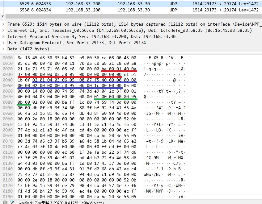
And the PC will not receive any data from Ethernet.
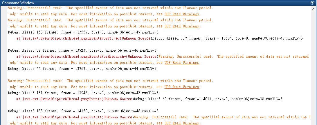
3. Sometimes, the GUI print the frame lost issue.
Could you give me advice?
Thanks
Morris
fig.1
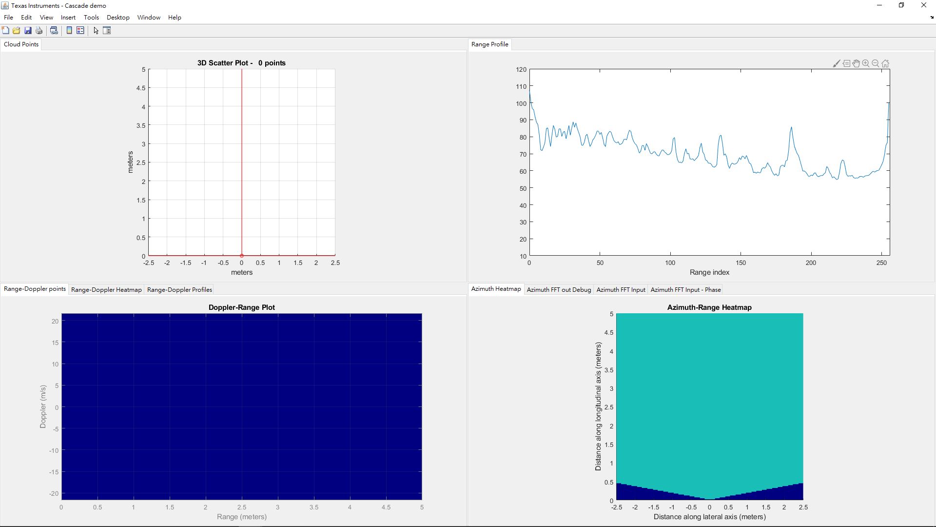
fig.2