This thread has been locked.

If you have a related question, please click the "Ask a related question" button in the top right corner. The newly created question will be automatically linked to this question.

TIDEP-01017: AWR1243 Cascade: MIPI CSI-2 Interface signal integrity

Part Number: TIDEP-01017
Other Parts Discussed in Thread: TDA2, MMWCAS-DSP-EVM, AWR1243

Hi,

We are trying to bring up one of our custom boards that uses two AWR1243 in cascade mode. This is interfaced with a TDA2 board (MMWCAS-DSP-EVM). Our initial tests with mmWave Studio 02.01.00.00 have all been successful. We are now wanting to move to an online data acquisition / data processing pipeline. We are using Processor SDK 3.7 Radar package for this purpose. We use one of the sample use cases provided as our starting point and customized it to enable our 2-chip cascade setup. However we are observing that data from one of the chips (slave device) is not entering the data processing chain.

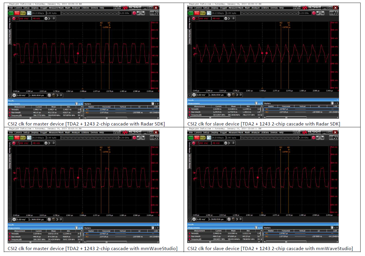
We probed the CSI-2 lanes on both the devices and identified that the 300 MHz CSI-2 clock signal on the slave device is skewed when compared to the master device. More specifically, the rise time is observed to be ~1.3 ns on the slave device compared to ~450 ps on the master device. The same experiments when using mmWave Studio produce very similar CSI-2 clocks (rise time of ~440-500 ps) on both master and slave devices, which leads us to believe that some configuration in the Radar SDK is causing this issue. Please see below screenshots of the measurements captured.

Could you please advice as to what could be causing this discrepancy when we switch software frameworks?

Thanks,

Siddharth

  • Hi Siddharth,

    In Radar SDK implementation, it checks the cascade RF board revision to determine SPI port assignment.

    If it doesn't find the EEPROM for board revision, it will assume the McSPI1 (instance 0) / channel 0 is for Master and McSPI1 / channel 1 is for Slave1.

    Otherwise, it assign McSPI1/ch0 for Master and McSPI2/ch0 for Slave1.

    Could you first make sure you have the McSPI assignment set correctly for the custom board? 

    Regards,
    Stanley

  • Hi Stanley,

    Thanks for your reply. We checked the McSPI initialization and confirmed that device 0 (master) is using McSPI1 / channel 0 and device 1 (slave) is using McSPI2 / channel 0

    We also checked that the firmware is loaded correctly on both devices (confirming SPI setup is correct).

    Below is a log of our boot up sequence. 

    [IPU1-0] 9.026993 s: CHAINS: Init AR12xx ...
    [IPU1-0] 9.027084 s: Device 0 uses McSPI1->0,0 ...
    [IPU1-0] 9.027359 s: UTILS_MCSPI: McSPI is configured in interrupt mode!!
    [IPU1-0] 9.027786 s: Device 1 with board rev 5 uses McSPI2->1,0 ...
    [IPU1-0] 9.027938 s: UTILS_MCSPI: McSPI is configured in interrupt mode!!

    Device 0
    [IPU1-0] 16.858781 s: AWR12XX: Version Master : 1.10.0.20
    [IPU1-0] 16.858872 s: AWR12XX: Version RF:2.0.0.1
    [IPU1-0] 16.858994 s: AWR12XX: Version mmWaveLink:1.2.0.0
    [IPU1-0] 16.859116 s: AWR12XX: Version Master Patch[dd.mm.yy]:14.9.18
    [IPU1-0] 16.859269 s: AWR12XX: Version RF Patch[dd.mm.yy]:14.9.18

    Device 1
    [IPU1-0] 16.861068 s: AWR12XX: Version Master : 1.10.0.20
    [IPU1-0] 16.861251 s: AWR12XX: Version RF:2.0.0.1
    [IPU1-0] 16.861343 s: AWR12XX: Version mmWaveLink:1.2.0.0
    [IPU1-0] 16.861434 s: AWR12XX: Version Master Patch[dd.mm.yy]:14.9.18
    [IPU1-0] 16.861556 s: AWR12XX: Version RF Patch[dd.mm.yy]:14.9.18

    Is there anything else that could be affecting the CSI2-data when moving from mmWave Studio to Radar SDK

    Thanks,

    Siddharth

  • Hi Siddharth,

    Could you double check the waveform for Slave1 again and make sure the probe has proper ground connection?

    Poor/unstable ground connection could also cause the waveform to look like what you have captured.

    Regards,
    Stanley

  • Hi Siddharth,

    I would also recommend you to use Processor SDK 3.8 release, instead of 3.7.

    There are 2 configuration issues fixed in 3.8 release. Those 2 issues are probably not be related to your current problem but will be an issue with radar data integrity once data is received and being processed.

    Regards,
    Stanley

  • Hi Stanley,

    We were able to capture the CSI-2 data using both mmWave Studio and Processor SDK and we observe a similar pattern. That is when using mmWave Studio, the data on lane 0 for both master and slave looks similar. But when we switch to Processor SDK the data from the slave appears noisy and Vpp is almost double that of the master. Please see below snapshot. We are pretty confident that the differential probe we are using is well connected to the test points of our board when conducting these experiments.

    Thanks,

    Siddharth

  • Could you use the same configuration on TI 4-chip Cascade RF board and see if you notice the same behavior?

  • Hi Stanley,

    We were able to resolve the issue. Basically, in the SDK the FPGA numbering is a function of numRadars which we changed to 2 to support our board. 

    However, within ChainsCommon_fpgaStart, the ordering is FPGA1,2,3,0 so for our case the concerned FPGA was not turning on.

    We modified the code, and also mapped the VIP ports/slices correctly and we are now able to see end to end data flow for our use case. We also measured the clk again on the slave device and it looks similar to the master device which confirms the hypothesis regarding the FPGA not being enabled.

    Thanks,

    Siddharth