This thread has been locked.

If you have a related question, please click the "Ask a related question" button in the top right corner. The newly created question will be automatically linked to this question.

DRA726: Unused balls and SysConfig

Part Number: DRA726
Other Parts Discussed in Thread: SYSCONFIG

Hi all,

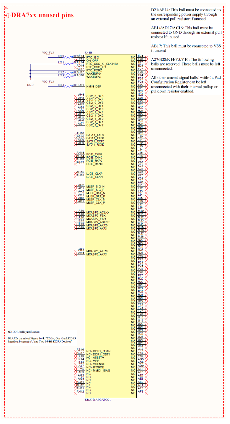
I have a DRA726 with the following unused balls:

I've followed the "Unused Balls Connection Requirements" section in DRA726 datasheet and while everything is crystal clear in the HW side, I have some doubts in the SW side regarding the following note:

"All other unused signal balls with a Pad Configuration register can be left unconnected with
their internal pullup or pulldown resistor enabled"

I've seen SysConfig generates the required config files regarding the USED balls, but it does not generate any output file regarding the UNUSED ones. So.. How I'm supposed to configure the PU/PD of the unused balls, like ON_OFF?

  • Should I configure the unused balls on the fly while the DRA is booting?
  • Should I set up the peripherals I won't use in SysConfig the same way I configure the ones I'use to include them in the output files?

Thank you very much in advance!

  • You can check the default state of the IO, its possible some may default with PU or PD enabled.  Another option might be to configure as GPIO (input) for unused signals - and then enable the internal PU.  

    I've asked to loop in additional resources to help answer.

  • Hi Robert, thank you very much for your answer.

    • The GPIO option you talk about is what I actually use for all the unused balls that can be multiplexed as GPIOs. However, the balls I talk about can't be configured in that way.
    • I'll take a look to the default IO states you mention while you recollect the additional info!

    Regards,

  • Can you provide specifics on which unused pins in your design do not have GPIO mux option?  Its possible those pins can be left open, and do not require PU or PD.

  • Hi Robert,

    You can find them in the previously attached picture. All the pin at the left side of the sch symbol labeled with something else than "NC" are unused pins with no GPIO mux option. As an example:

    • ON_OFF (Y11)
    • CSI2_0_DX3 (AH4)
    • MCASP5_AXR0 (AB3)
    • NC - DDR1_CS1N (AB16)

    Regards,

  • Guillermo Corrales said:
    • CSI2_0_DX3 (AH4)
    • NC - DDR1_CS1N (AB16)

    These two pins do not have a pad configuration register.  The proper termination of these signals is described by this note:

    All other unused signal balls without a Pad Configuration register can be left unconnected.

    Guillermo Corrales said:
    • ON_OFF (Y11)
    • MCASP5_AXR0 (AB3)

    The ON_OFF signal has a pad config register: CTRL_CORE_PAD_ON_OFF.  It has a pullup enabled by default, so no further software intervention is needed to follow this note:

    All other unused signal balls with a Pad Configuration register can be left unconnected with
    their internal pullup or pulldown resistor enabled.

    MCASP5_AXR0 has pad config register CTRL_CORE_PAD_MCASP5_AXR0 which defaults to pulldown enabled, so no further software intervention is needed.

  • Hi Brad,

    Understood, I assume it is just a matter of checking the default state of all the unconnected balls to confirm they have by default their internal PU/PD enabled. But what about if an unused ball doesn't have any of them enabled by default? Is this a possible situation? I'm going to check my unused pins and if all of them have a PU/PD enabled (or they don't have a pad config register) I will come back to set this thread as solved.

    Regards,

  • For this particular device, the only pins that don't have an internal pullup/pulldown active by default are the gpmc_ad[15:0] pins and the rtck pin.  Double check those pins in particular.