This thread has been locked.

If you have a related question, please click the "Ask a related question" button in the top right corner. The newly created question will be automatically linked to this question.

TMDSEMU560V2STM-UE: TMDSEMU560V2STM-UE failed in use

Part Number: TMDSEMU560V2STM-UE
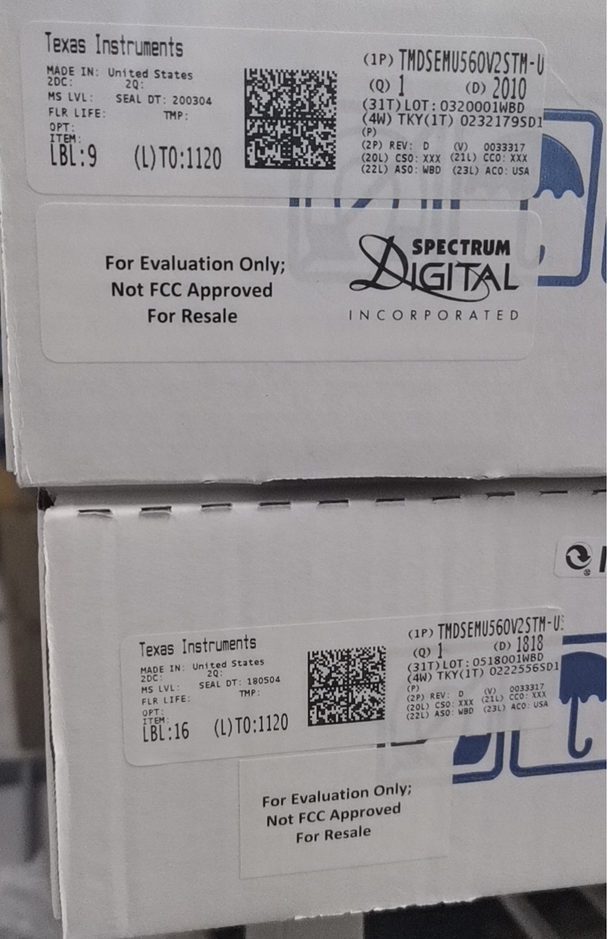
Other Parts Discussed in Thread: TMDSEMU560V2STM-U

我们买了四个仿真器,分别是两个TMDSEMU560V2STM-UE(#1,#2),两个TMDSEMU560V2STM-U(#3,#4)。用了一段时间,有三个出了问题,只有一个还在正常使用中。(#1,#2,#3,#4是我给仿真器编的号)

四个仿真器出现的情况如下:

编 号#1:型号是TMDSEMU560V2STM-UE,是一个有源仿真器,接上电源和USB连线后,LED无任何响应(不亮,不闪),使用Sd560v2Config也无任何响应。

编 号#2:型号是TMDSEMU560V2STM-UE,接上电源和USB线后,LED正常闪烁并能进入正常状态,使用Sd560v2Config软件进行测 试,可以检测到仿真器,也可以进行USB回环测试,进行DbgJtag测试时, 第一个RESET项就不能通过,错误信息是:error-182,大意是连接电缆断开,但是反复检查,电缆都是好的,就是无法连接目标板。

编 号#3:型号是TMDSEMU560V2STM-U,可以正常工作,正常连接目标板。使用Bh560v2Config Utility软件,可以检测到仿真器,并可以进行所有操作。

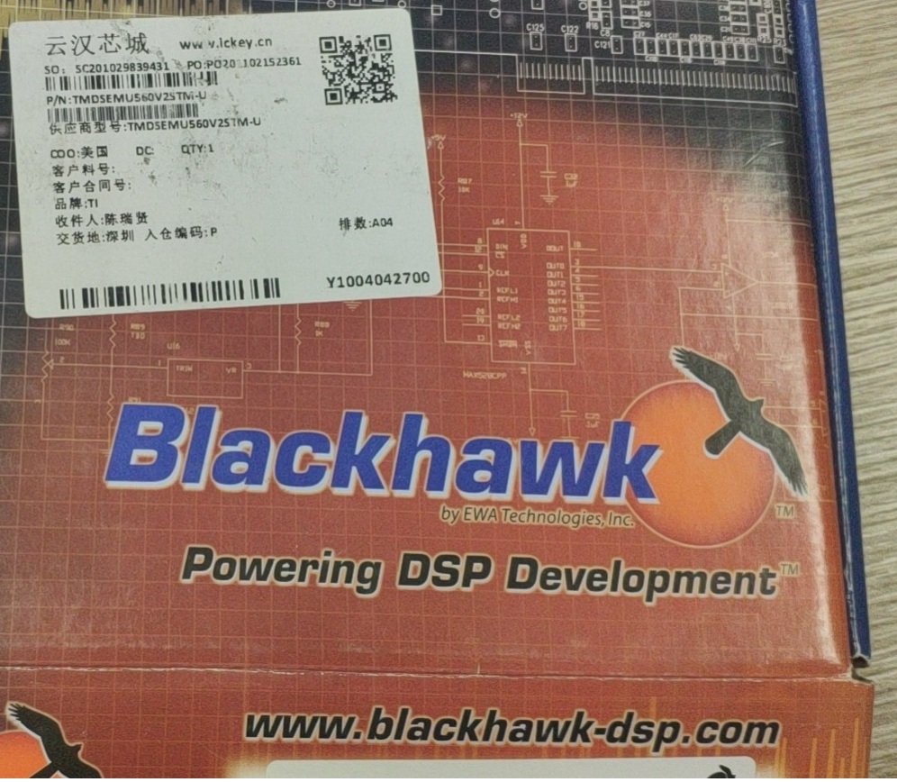
编 号#4:型号是TMDSEMU560V2STM-U, (BlackHawk ),连接USB电缆后,两个LED均不亮,使用Bh560v2Config Utility软件测试,不能检测到仿真器。


这个仿真器我反反复复进行测试了两三周了,也读了很多TI官网相关文件资料,始终无法取得任何进展,恳切希望您能帮忙解决我的问题。

同时,我觉得有这三个仿真器我自己是无法处理的,我希望能够将他们返厂维修,希望您能为我打开这个渠道,谢谢您。


附件为视频


We bought 4 emulations from www.ickey.cn, their models are TMDSEMU560V2STM-UE(#1,#2)and TMDSEMU560V2STM-U(#3,#4). Several days later, there are something wrong with 3 of them, only 1 of them can use normaly. ( I coding these 4 emulations with #1, #2,#3,#4)

Here are the situations of these emulations:

Coding number #1: Its model is TMDSEMU560V2STM-UE, it is a emulation with dedicate power supply. When I connect the power supply cable(power up) and USB cable, it has no any response, all LEDs are off. I test it with software 'Sd560v2Config', i got no response either.

Coding number #2: Its model is TMDSEMU560V2STM-UE also. I connect the power supply cable(power up) and USB cable, LEDs start blink and the emulations enters normal state.

   I test it with software 'Sd560v2Config', the software detects the emulation. I'v done several tests with USB cable:

USB loopback : pass

 USB print status: pass

         USB force EEOS: pass

   Then I use 'DbgJtag' test page test the emulation, I got a error info"error-182" when i use 'RESET' command. The explanation is:

            The controller has detected a cable break that is near-to itself.

      The user must connect the cable/pod to the controller.

   I checked the cable for several times, there is nothing wrong with it.

Coding number #3: Its model is TMDSEMU560V2STM-U, it can work normal now. I am very glad that I still have a good emulation to work with my target board. Software 'Bh560v2Config Utility' can detect it , and passes every test.

Coding number #4: Its model is TMDSEMU560V2STM-U. No led become on when I connect the USB cable with it, no response! Software 'Bh560v2Config Utility' cannot find it.


I test these emulations for weeks, and I have read many technical documentations from TI website, but I got no progress. I fell exhausted!

I think I can't correct these errors. Maybe they should be returns to the factory  and be repaired.

CAN you help me?

Thank you anyway.

attach several visions as attachments.


  • Hello,

    user6476790 said:
    We bought 4 emulations from www.ickey.cn, their models are TMDSEMU560V2STM-UE(#1,#2)and TMDSEMU560V2STM-U(#3,#4). Several days later, there are something wrong with 3 of them, only 1 of them can use normaly. ( I coding these 4 emulations with #1, #2,#3,#4)

    Sorry to hear of your bad experience with these debug probes.

    user6476790 said:
    Coding number #1: Its model is TMDSEMU560V2STM-UE, it is a emulation with dedicate power supply. When I connect the power supply cable(power up) and USB cable, it has no any response, all LEDs are off. I test it with software 'Sd560v2Config', i got no response either.

    This probe appears to be dead. At minimum, the power LED should light up if correct power is applied to the debug probe (even if the probe is not connected to the PC). This probe likely needs to be returned

    user6476790 said:

    Coding number #2: Its model is TMDSEMU560V2STM-UE also. I connect the power supply cable(power up) and USB cable, LEDs start blink and the emulations enters normal state.

       I test it with software 'Sd560v2Config', the software detects the emulation. I'v done several tests with USB cable:

    USB loopback : pass

     USB print status: pass

             USB force EEOS: pass

       Then I use 'DbgJtag' test page test the emulation, I got a error info"error-182" when i use 'RESET' command. The explanation is:

                The controller has detected a cable break that is near-to itself.

          The user must connect the cable/pod to the controller.

       I checked the cable for several times, there is nothing wrong with it.

    Note that the 'dbgjtag' test in the SD560v2Config utility is to test the JTAG connection between the debug probe and the target board. Based on your second video, it looks like the probe is not connected to a target board. Hence the -182 error is expected. When the error is complaining about a "cable break", it is the cable between the debug probe to the target board it is complaining about and NOT the USB cable from the PC to debug probe.

    user6476790 said:
    Coding number #3: Its model is TMDSEMU560V2STM-U, it can work normal now. I am very glad that I still have a good emulation to work with my target board. Software 'Bh560v2Config Utility' can detect it , and passes every test.

    Looks good.

    user6476790 said:
    Coding number #4: Its model is TMDSEMU560V2STM-U. No led become on when I connect the USB cable with it, no response! Software 'Bh560v2Config Utility' cannot find it.

    This probe appears to be dead. At minimum, the USB LED should light up red when the USB cable is connected from the PC to the debug probe. If it does not light up at all, then the probe is not being powered up. This probe likely needs to be returned.

    ki

  • Receiving your reply is a good news after my vacation.

    Thank you very much for your detailed answer.


    For coding number #2: I connect the emulator to the target board which is tested good by other emulator. I test the emulator with 'Sd560v2Config', the software detects the emulator. And test results are as follows:

       USB loopback : pass

       USB print status: pass

             USB force EEOS: pass

       Then I use 'DbgJtag' test page to test the emulator, I got a error info"error-182" when I use 'RESET' command.


        There should be something wrong with it ,I think.

        Would you please give me some advice。

        Thank you,sincerely.

         The vision is attached.

  • Can you post the complete results of the JTAG connectivity test in CCS?

    https://dev.ti.com/tirex/explore/node?node=AMCrhRy9n80ZsUrBFVdo1Q__FUz-xrs__LATEST

    You can copy&paste the results to a text file and then attach the file.

    Thanks

    ki 

  • HELLO , I test my emulators according  to  the steps  in that vision.

    Here is the result:

    Please check it. 

    Thank YOU!

    /*********************************************************************************************/

    (1)TEST 1

    THis TEST proves the target is good.

    /*********************************************************************************************/

    [Start: Blackhawk XDS560v2-USB System Trace Emulator_0]

    Execute the command:

    %ccs_base%/common/uscif/dbgjtag.exe -f %boarddatafile% -rv -o -F inform,logfile=yes -S pathlength -S integrity

    [Result]


    -----[Print the board config pathname(s)]------------------------------------

    C:\Users\VIM-008\AppData\Local\TEXASI~1\
    CCS\ccs901\0\0\BrdDat\testBoard.dat

    -----[Print the reset-command software log-file]-----------------------------

    This utility has selected a 560/2xx-class product.
    This utility will load the program 'bh560v2u.out'.
    Loaded FPGA Image: C:\ti\ccs901\ccs\ccs_base\common\uscif\dtc_top.jbc
    The library build date was 'Mar 25 2019'.
    The library build time was '14:47:27'.
    The library package version is '8.1.0.00007'.
    The library component version is '35.35.0.0'.
    The controller does not use a programmable FPGA.
    The controller has a version number of '6' (0x00000006).
    The controller has an insertion length of '0' (0x00000000).
    The cable+pod has a version number of '8' (0x00000008).
    The cable+pod has a capability number of '7423' (0x00001cff).
    This utility will attempt to reset the controller.
    This utility has successfully reset the controller.

    -----[Print the reset-command hardware log-file]-----------------------------

    The scan-path will be reset by toggling the JTAG TRST signal.
    The controller is the Nano-TBC VHDL.
    The link is a 560-class second-generation-560 cable.
    The software is configured for Nano-TBC VHDL features.
    The controller will be software reset via its registers.
    The controller has a logic ONE on its EMU[0] input pin.
    The controller has a logic ONE on its EMU[1] input pin.
    The controller will use falling-edge timing on output pins.
    The controller cannot control the timing on input pins.
    The scan-path link-delay has been set to exactly '2' (0x0002).
    The utility logic has not previously detected a power-loss.
    The utility logic is not currently detecting a power-loss.
    Loaded FPGA Image: C:\ti\ccs901\ccs\ccs_base\common\uscif\dtc_top.jbc

    -----[The log-file for the JTAG TCLK output generated from the PLL]----------

    Test Size Coord MHz Flag Result Description
    ~~~~ ~~~~ ~~~~~~~ ~~~~~~~~ ~~~~ ~~~~~~~~~~~ ~~~~~~~~~~~~~~~~~~~
    1 none - 01 00 500.0kHz - similar isit internal clock
    2 none - 01 09 570.3kHz - similar isit internal clock
    3 64 - 01 00 500.0kHz O good value measure path length
    4 16 - 01 00 500.0kHz O good value auto step initial
    5 16 - 01 0D 601.6kHz O good value auto step delta
    6 16 - 01 1C 718.8kHz O good value auto step delta
    7 16 - 01 2E 859.4kHz O good value auto step delta
    8 16 + 00 02 1.031MHz O good value auto step delta
    9 16 + 00 0F 1.234MHz O good value auto step delta
    10 16 + 00 1F 1.484MHz O good value auto step delta
    11 16 + 00 32 1.781MHz O good value auto step delta
    12 16 + 01 04 2.125MHz O good value auto step delta
    13 16 + 01 11 2.531MHz O good value auto step delta
    14 16 + 01 21 3.031MHz O good value auto step delta
    15 16 + 01 34 3.625MHz O good value auto step delta
    16 16 + 02 05 4.313MHz O good value auto step delta
    17 16 + 02 13 5.188MHz O good value auto step delta
    18 16 + 02 23 6.188MHz O good value auto step delta
    19 16 + 02 37 7.438MHz O good value auto step delta
    20 16 + 03 07 8.875MHz O good value auto step delta
    21 16 + 03 15 10.63MHz O good value auto step delta
    22 16 + 03 1E 11.75MHz {O} good value auto step delta
    23 64 + 02 3E 7.875MHz O good value auto power initial
    24 64 + 03 0E 9.750MHz O good value auto power delta
    25 64 + 03 16 10.75MHz O good value auto power delta
    26 64 + 03 1A 11.25MHz O good value auto power delta
    27 64 + 03 1C 11.50MHz O good value auto power delta
    28 64 + 03 1D 11.63MHz O good value auto power delta
    29 64 + 03 1D 11.63MHz O good value auto power delta
    30 64 + 03 13 10.38MHz {O} good value auto margin initial

    The first internal/external clock test resuts are:
    The expect frequency was 500000Hz.
    The actual frequency was 499110Hz.
    The delta frequency was 890Hz.

    The second internal/external clock test resuts are:
    The expect frequency was 570312Hz.
    The actual frequency was 569976Hz.
    The delta frequency was 336Hz.

    In the scan-path tests:
    The test length was 2048 bits.
    The JTAG IR length was 6 bits.
    The JTAG DR length was 1 bits.

    The IR/DR scan-path tests used 30 frequencies.
    The IR/DR scan-path tests used 500.0kHz as the initial frequency.
    The IR/DR scan-path tests used 11.75MHz as the highest frequency.
    The IR/DR scan-path tests used 10.38MHz as the final frequency.

    -----[Measure the source and frequency of the final JTAG TCLKR input]--------

    The frequency of the JTAG TCLKR input is measured as 10.37MHz.

    The frequency of the JTAG TCLKR input and TCLKO output signals are similar.
    The target system likely uses the TCLKO output from the emulator PLL.

    -----[Perform the standard path-length test on the JTAG IR and DR]-----------

    This path-length test uses blocks of 64 32-bit words.

    The test for the JTAG IR instruction path-length succeeded.
    The JTAG IR instruction path-length is 6 bits.

    The test for the JTAG DR bypass path-length succeeded.
    The JTAG DR bypass path-length is 1 bits.

    -----[Perform the Integrity scan-test on the JTAG IR]------------------------

    This test will use blocks of 64 32-bit words.
    This test will be applied just once.

    Do a test using 0xFFFFFFFF.
    Scan tests: 1, skipped: 0, failed: 0
    Do a test using 0x00000000.
    Scan tests: 2, skipped: 0, failed: 0
    Do a test using 0xFE03E0E2.
    Scan tests: 3, skipped: 0, failed: 0
    Do a test using 0x01FC1F1D.
    Scan tests: 4, skipped: 0, failed: 0
    Do a test using 0x5533CCAA.
    Scan tests: 5, skipped: 0, failed: 0
    Do a test using 0xAACC3355.
    Scan tests: 6, skipped: 0, failed: 0
    All of the values were scanned correctly.

    The JTAG IR Integrity scan-test has succeeded.

    -----[Perform the Integrity scan-test on the JTAG DR]------------------------

    This test will use blocks of 64 32-bit words.
    This test will be applied just once.

    Do a test using 0xFFFFFFFF.
    Scan tests: 1, skipped: 0, failed: 0
    Do a test using 0x00000000.
    Scan tests: 2, skipped: 0, failed: 0
    Do a test using 0xFE03E0E2.
    Scan tests: 3, skipped: 0, failed: 0
    Do a test using 0x01FC1F1D.
    Scan tests: 4, skipped: 0, failed: 0
    Do a test using 0x5533CCAA.
    Scan tests: 5, skipped: 0, failed: 0
    Do a test using 0xAACC3355.
    Scan tests: 6, skipped: 0, failed: 0
    All of the values were scanned correctly.

    The JTAG DR Integrity scan-test has succeeded.

    [End: Blackhawk XDS560v2-USB System Trace Emulator_0]

    /*********************************************************************************************/

    2)Test 2

    This test used to check the problem emulator.

    It  stoped with some errors

    /*********************************************************************************************/

    [Start: Spectrum Digital XDS560V2 STM USB Emulator_0]

    Execute the command:

    %ccs_base%/common/uscif/dbgjtag -f %boarddatafile% -rv -o -F inform,logfile=yes -S pathlength -S integrity

    [Result]


    -----[Print the board config pathname(s)]------------------------------------

    C:\Users\VIM-008\AppData\Local\TEXASI~1\
    CCS\ccs901\0\0\BrdDat\testBoard.dat

    -----[Print the reset-command software log-file]-----------------------------

    This utility has selected a 560/2xx-class product.
    This utility will load the program 'sd560v2u.out'.
    Loaded FPGA Image: C:\ti\ccs901\ccs\ccs_base\common\uscif\dtc_top.jbc
    The library build date was 'Mar 25 2019'.
    The library build time was '14:47:27'.
    The library package version is '8.1.0.00007'.
    The library component version is '35.35.0.0'.
    The controller does not use a programmable FPGA.

    An error occurred while hard opening the controller.

    -----[An error has occurred and this utility has aborted]--------------------

    This error is generated by TI's USCIF driver or utilities.

    The value is '-182' (0xffffff4a).
    The title is 'SC_ERR_CTL_CBL_BREAK_NEAR'.

    The explanation is:
    The controller has detected a cable break that is near-to itself.
    The user must connect the cable/pod to the controller.

    [End: Spectrum Digital XDS560V2 STM USB Emulator_0]

    BH560V2 Test recorder 20210304.txt
    PS:THis TEST proves the target is good.


    [Start: Blackhawk XDS560v2-USB System Trace Emulator_0]
    
    Execute the command:
    
    %ccs_base%/common/uscif/dbgjtag.exe -f %boarddatafile% -rv -o -F inform,logfile=yes -S pathlength -S integrity
    
    [Result]
    
    
    -----[Print the board config pathname(s)]------------------------------------
    
    C:\Users\VIM-008\AppData\Local\TEXASI~1\
        CCS\ccs901\0\0\BrdDat\testBoard.dat
    
    -----[Print the reset-command software log-file]-----------------------------
    
    This utility has selected a 560/2xx-class product.
    This utility will load the program 'bh560v2u.out'.
    Loaded FPGA Image: C:\ti\ccs901\ccs\ccs_base\common\uscif\dtc_top.jbc
    The library build date was 'Mar 25 2019'.
    The library build time was '14:47:27'.
    The library package version is '8.1.0.00007'.
    The library component version is '35.35.0.0'.
    The controller does not use a programmable FPGA.
    The controller has a version number of '6' (0x00000006).
    The controller has an insertion length of '0' (0x00000000).
    The cable+pod has a version number of '8' (0x00000008).
    The cable+pod has a capability number of '7423' (0x00001cff).
    This utility will attempt to reset the controller.
    This utility has successfully reset the controller.
    
    -----[Print the reset-command hardware log-file]-----------------------------
    
    The scan-path will be reset by toggling the JTAG TRST signal.
    The controller is the Nano-TBC VHDL.
    The link is a 560-class second-generation-560 cable.
    The software is configured for Nano-TBC VHDL features.
    The controller will be software reset via its registers.
    The controller has a logic ONE on its EMU[0] input pin.
    The controller has a logic ONE on its EMU[1] input pin.
    The controller will use falling-edge timing on output pins.
    The controller cannot control the timing on input pins.
    The scan-path link-delay has been set to exactly '2' (0x0002).
    The utility logic has not previously detected a power-loss.
    The utility logic is not currently detecting a power-loss.
    Loaded FPGA Image: C:\ti\ccs901\ccs\ccs_base\common\uscif\dtc_top.jbc
    
    -----[The log-file for the JTAG TCLK output generated from the PLL]----------
    
      Test  Size   Coord      MHz    Flag  Result       Description
      ~~~~  ~~~~  ~~~~~~~  ~~~~~~~~  ~~~~  ~~~~~~~~~~~  ~~~~~~~~~~~~~~~~~~~
        1   none  - 01 00  500.0kHz   -    similar      isit internal clock
        2   none  - 01 09  570.3kHz   -    similar      isit internal clock
        3     64  - 01 00  500.0kHz   O    good value   measure path length
        4     16  - 01 00  500.0kHz   O    good value   auto step initial
        5     16  - 01 0D  601.6kHz   O    good value   auto step delta
        6     16  - 01 1C  718.8kHz   O    good value   auto step delta
        7     16  - 01 2E  859.4kHz   O    good value   auto step delta
        8     16  + 00 02  1.031MHz   O    good value   auto step delta
        9     16  + 00 0F  1.234MHz   O    good value   auto step delta
       10     16  + 00 1F  1.484MHz   O    good value   auto step delta
       11     16  + 00 32  1.781MHz   O    good value   auto step delta
       12     16  + 01 04  2.125MHz   O    good value   auto step delta
       13     16  + 01 11  2.531MHz   O    good value   auto step delta
       14     16  + 01 21  3.031MHz   O    good value   auto step delta
       15     16  + 01 34  3.625MHz   O    good value   auto step delta
       16     16  + 02 05  4.313MHz   O    good value   auto step delta
       17     16  + 02 13  5.188MHz   O    good value   auto step delta
       18     16  + 02 23  6.188MHz   O    good value   auto step delta
       19     16  + 02 37  7.438MHz   O    good value   auto step delta
       20     16  + 03 07  8.875MHz   O    good value   auto step delta
       21     16  + 03 15  10.63MHz   O    good value   auto step delta
       22     16  + 03 1E  11.75MHz  {O}   good value   auto step delta
       23     64  + 02 3E  7.875MHz   O    good value   auto power initial
       24     64  + 03 0E  9.750MHz   O    good value   auto power delta
       25     64  + 03 16  10.75MHz   O    good value   auto power delta
       26     64  + 03 1A  11.25MHz   O    good value   auto power delta
       27     64  + 03 1C  11.50MHz   O    good value   auto power delta
       28     64  + 03 1D  11.63MHz   O    good value   auto power delta
       29     64  + 03 1D  11.63MHz   O    good value   auto power delta
       30     64  + 03 13  10.38MHz  {O}   good value   auto margin initial
    
    The first internal/external clock test resuts are:
    The expect frequency was 500000Hz.
    The actual frequency was 499110Hz.
    The delta frequency was 890Hz.
    
    The second internal/external clock test resuts are:
    The expect frequency was 570312Hz.
    The actual frequency was 569976Hz.
    The delta frequency was 336Hz.
    
    In the scan-path tests:
    The test length was 2048 bits.
    The JTAG IR length was 6 bits.
    The JTAG DR length was 1 bits.
    
    The IR/DR scan-path tests used 30 frequencies.
    The IR/DR scan-path tests used 500.0kHz as the initial frequency.
    The IR/DR scan-path tests used 11.75MHz as the highest frequency.
    The IR/DR scan-path tests used 10.38MHz as the final frequency.
    
    -----[Measure the source and frequency of the final JTAG TCLKR input]--------
    
    The frequency of the JTAG TCLKR input is measured as 10.37MHz.
    
    The frequency of the JTAG TCLKR input and TCLKO output signals are similar.
    The target system likely uses the TCLKO output from the emulator PLL.
    
    -----[Perform the standard path-length test on the JTAG IR and DR]-----------
    
    This path-length test uses blocks of 64 32-bit words.
    
    The test for the JTAG IR instruction path-length succeeded.
    The JTAG IR instruction path-length is 6 bits.
    
    The test for the JTAG DR bypass path-length succeeded.
    The JTAG DR bypass path-length is 1 bits.
    
    -----[Perform the Integrity scan-test on the JTAG IR]------------------------
    
    This test will use blocks of 64 32-bit words.
    This test will be applied just once.
    
    Do a test using 0xFFFFFFFF.
    Scan tests: 1, skipped: 0, failed: 0
    Do a test using 0x00000000.
    Scan tests: 2, skipped: 0, failed: 0
    Do a test using 0xFE03E0E2.
    Scan tests: 3, skipped: 0, failed: 0
    Do a test using 0x01FC1F1D.
    Scan tests: 4, skipped: 0, failed: 0
    Do a test using 0x5533CCAA.
    Scan tests: 5, skipped: 0, failed: 0
    Do a test using 0xAACC3355.
    Scan tests: 6, skipped: 0, failed: 0
    All of the values were scanned correctly.
    
    The JTAG IR Integrity scan-test has succeeded.
    
    -----[Perform the Integrity scan-test on the JTAG DR]------------------------
    
    This test will use blocks of 64 32-bit words.
    This test will be applied just once.
    
    Do a test using 0xFFFFFFFF.
    Scan tests: 1, skipped: 0, failed: 0
    Do a test using 0x00000000.
    Scan tests: 2, skipped: 0, failed: 0
    Do a test using 0xFE03E0E2.
    Scan tests: 3, skipped: 0, failed: 0
    Do a test using 0x01FC1F1D.
    Scan tests: 4, skipped: 0, failed: 0
    Do a test using 0x5533CCAA.
    Scan tests: 5, skipped: 0, failed: 0
    Do a test using 0xAACC3355.
    Scan tests: 6, skipped: 0, failed: 0
    All of the values were scanned correctly.
    
    The JTAG DR Integrity scan-test has succeeded.
    
    [End: Blackhawk XDS560v2-USB System Trace Emulator_0]
    
    spectrum digital XDS560V2 STM UE test recorder 20210304.txt


    [Start: Spectrum Digital XDS560V2 STM USB Emulator_0]
    
    Execute the command:
    
    %ccs_base%/common/uscif/dbgjtag -f %boarddatafile% -rv -o -F inform,logfile=yes -S pathlength -S integrity
    
    [Result]
    
    
    -----[Print the board config pathname(s)]------------------------------------
    
    C:\Users\VIM-008\AppData\Local\TEXASI~1\
        CCS\ccs901\0\0\BrdDat\testBoard.dat
    
    -----[Print the reset-command software log-file]-----------------------------
    
    This utility has selected a 560/2xx-class product.
    This utility will load the program 'sd560v2u.out'.
    Loaded FPGA Image: C:\ti\ccs901\ccs\ccs_base\common\uscif\dtc_top.jbc
    The library build date was 'Mar 25 2019'.
    The library build time was '14:47:27'.
    The library package version is '8.1.0.00007'.
    The library component version is '35.35.0.0'.
    The controller does not use a programmable FPGA.
    
    An error occurred while hard opening the controller.
    
    -----[An error has occurred and this utility has aborted]--------------------
    
    This error is generated by TI's USCIF driver or utilities.
    
    The value is '-182' (0xffffff4a).
    The title is 'SC_ERR_CTL_CBL_BREAK_NEAR'.
    
    The explanation is:
    The controller has detected a cable break that is near-to itself.
    The user must connect the cable/pod to the controller.
    
    [End: Spectrum Digital XDS560V2 STM USB Emulator_0]
    

  • Thanks.

    user6476790 said:
    The value is '-182' (0xffffff4a).
    The title is 'SC_ERR_CTL_CBL_BREAK_NEAR'.

    Regarding the above error, please see:

    https://software-dl.ti.com/ccs/esd/documents/ccs_debugging_jtag_connectivity_issues.html#cable-break

    Specifically see:

    Technically a cable break is detected by a pin that is grounded when the cable is plugged in. If the pin is on the connector that plugs into the target board, it is often called Cable Break Far or sometimes just Cable Break. If the pin is on the connector that plugs into the debug probe (e.g. the cable pod of an XDS560v2), that is called Cable Break Near.

    Check the integrity of the ribbon cable that connects from the pod to the board. Check the connections to the mentioned pin. If you have a spare cable (maybe from the broken pod), you may want to swap out the existing one with the spare. 

    Thanks

    ki