Hi,
Because I need two bt1120 interfaces with the same configuration, I need to enable both vout0 / DP0 and Vout1 / DP1. Now the vout0 / DP0 interface can be used normally, but Vout1 / DP1 has problems all the time.The following is the configuration of the two BT interfaces:
1、pinumux: I use the pinmux configured by the ti-pinmux tool, so I'm sure that's right.
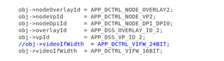
2、app_dctrl.h:
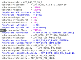
3、app_dss_defaults.c
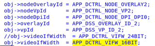
·VOUT0/DP0
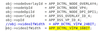
·VOUT1/DP1
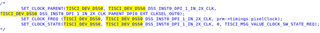
4、app_dss_j721e.c
·VOUT0/DP0
·VOUT1/DP1

I enable one BT at a time, because I use single display to test. The register configuration for each test is as follows:
1、VOU0/DP0(74.25MHz 16bit)
·DSS0_VP_CONFIG(04AA0000): 03200000
·DSS0_COMMON_DISPC_CONNECTIONS(04A000E4): 00000002
·DSS0_VP_POL_FREQ(04AA004C): 00000000
·DSS0_VP_CONTROL(04AA0004): 00000141
2、VOU1/DP1(74.25MHz 16bit)
·DSS0_VP_CONFIG(04AE0000): 03200000
·DSS0_COMMON_DISPC_CONNECTIONS(04A000E4): 00000080
·DSS0_VP_POL_FREQ(04AE004C): 00000000
·DSS0_VP_CONTROL(04AE0004): 00000141
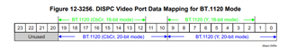
Because bt1120 will send background information when the system starts, I measured the data lines of two kinds of Vout, found a phenomenon ,as follow:
·data0, data4 and data15 in VOUT0 have data signals, but data2 and data6 in VOUT1 have data signals.
Is it the above phenomenon that causes Vout1 to be wrong all the time? If so, how to solve it? If not, how to locate the cause of the problem?
Looking forward to your reply!
Thank you!