This thread has been locked.

If you have a related question, please click the "Ask a related question" button in the top right corner. The newly created question will be automatically linked to this question.

TDA4VM: Serdes link diagnostics (SGMII)

Part Number: TDA4VM

Our custom board has several working serdes/sgmii interfaces, however one doesn't appear to work: I could use some guidance on what to investigate.

The errant interface is serdes 0 lane 1 (Sierra / 16-G), which we are configuring in PHY-less mode to another custom TDA4's using the exact same interface. At the SGMII level I have tried both AUTONEG_MASTER+AUTONET_SLAVE and FORCEDLINK modes with no luck, so I started looking at the lower level serdes configuration and registers.

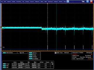
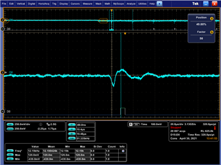
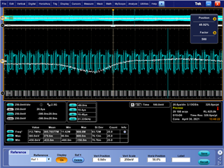
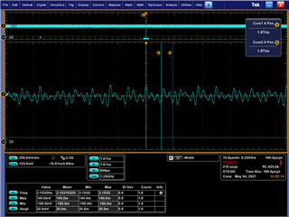
At the serdes level, I've observed that LANALIGN1 (0500 04C8h) on both sides is "hunting" for a value, indicating that it is unable to lock on to the signal from the remote side. While watching PHY_PMA_ISO_DATA_HI__PHY_PMA_ISO_DATA_LO_j (0500 F01Ch) I can disable the remote serdes using LANECTL1[31:30] and see a corresponding change from random values when enabled to just 0 when disabled.

What more should I investigate from here? Is there a way to configure the serdes to send only a single pattern and lock LANALIGN1 so I can observe the result in PMA_ISO_DATA?

  • Assuming the code is not periodically resetting the SGMII, a pause on all processors can confirm...

    If you are using the exactly same config at both ends, and the lane align is changing(hunting) I would investigate the refclk inputs. 

    There is a refclk mux that determines which internal source is used or a WIZ register which determine if the external reference is used.

    I am not sure if you are using the same board at both ends, if not, please check the reference resistor for the SERDES is installed. 

  • To help rule out interference from other cores, I've disabled serdes0 and related nodes in the Linux kernel, and for more certainty I also halted Linux on both boards leaving only the R5 MCU running on each. Seems to still be hunting around.

    I've also double-checked that Linux does not appear to be (as far as I can see) configuring any part of serdes0 its WIZ.

    In RTOS I'm configuring the ref-clocks in cpsw_appboardutils when the first SGMII interface is configured:

        CpswAppUtils_print("  SERDES_16G0\n");
        moduleId  = TISCI_DEV_SERDES_16G0;
        clkId     = TISCI_DEV_SERDES_16G0_CORE_REF1_CLK;
        clkRateHz = 100000000;
        CpswAppUtils_clkRateSet(moduleId, clkId, clkRateHz);
    
        clkId     = TISCI_DEV_SERDES_16G0_CORE_REF_CLK;
        clkRateHz = 100000000;
        CpswAppUtils_clkRateSet(moduleId, clkId, clkRateHz);
        CpswAppUtils_setDeviceState(moduleId, TISCI_MSG_VALUE_DEVICE_SW_STATE_ON, 0U);

    At the later layer in board_serdes_cfg, I'm calling CSL_serdesRefclkSel, CSL_serdesDisablePllAndLanes, CSL_serdesEthernetInit, CSL_serdesLaneEnable as like in j721e_evm's Board_CfgSgmii() with the following settings:

        serdesLaneEnableParams.serdesInstance = (CSL_SerdesInstance)CSL_SIERRA_SERDES0;
        serdesLaneEnableParams.baseAddr = CSL_SERDES_16G0_BASE;
        serdesLaneEnableParams.refClock = CSL_SERDES_REF_CLOCK_100M;
        serdesLaneEnableParams.refClkSrc = CSL_SERDES_REF_CLOCK_INT;
        serdesLaneEnableParams.linkRate = CSL_SERDES_LINK_RATE_1p25G;
        serdesLaneEnableParams.phyType = CSL_SERDES_PHY_TYPE_SGMII;
        serdesLaneEnableParams.phyInstanceNum = SERDES_LANE_SELECT_CPSW;
        serdesLaneEnableParams.laneCtrlRate[0] = CSL_SERDES_LANE_FULL_RATE;
        serdesLaneEnableParams.loopbackMode[0] = CSL_SERDES_LOOPBACK_DISABLED;
        serdesLaneEnableParams.laneCtrlRate[1] = CSL_SERDES_LANE_FULL_RATE;
        serdesLaneEnableParams.loopbackMode[1] = CSL_SERDES_LOOPBACK_DISABLED;
    

    Which, via CSL_serdesEthernetInit specifically, invokes csl_wiz16m_cs_refclk100MHz_20b_SGMII_cmn_pll & csl_wiz16m_cs_refclk100MHz_20b_SGMII_ln.

    I'm not sure where else I should be checking clocks? I've not yet tried to validate the signaling rate with a scope, but necessary I can...

  • Following up on your question of the reference resistor: According to schematic, yes: the same exact SOM is used on both ends of the connection (different carrier boards) and it appears that every SERDESn_REXT pin is connected to its own 3.01K resistor to DGND.

  • Is there any reason you cannot stop the R5 as well?

  • Sorry, yes: The R5 (running the vision_apps+ethfw software) was stopped when I made the observation: With Linux no longer running, I have to have CCS pause the R5 core so it can continuously read the registers.

  • OK, that is good. We have found in the past that some driver running elsewhere on the device was retrying stuff in the background causing these types of errors. One time it was the boot process

    So it looks like we are dealing with PLL frequency errors. can you scope the Tx or Rx data in both directions.

  • I can, but it will take a bit to setup (different lab and slightly different hardware configuration with Samtech cables instead of board-to-board mating)

    I should be able to respond w/ captures first thing in the morning Thumbsup

  • I'll keep an eye out for the update!

    AT 1G, the smallest data bit should be 800pS give or take a couple of pS.

  • I validated that I can observe SGMII from serdes 1 lane 0 which is going from J7 to a Marvel PHY, so I'm certain that I'm operating the scope correctly.

    First image is from J7-to-J7 SGMII (serdes 0 lane 1) (first half is me finding my way in closer to the caps):

    Next is a close up of the periodic blip (most likely interference?)

    And in this final image, the above waveform has been saved and recalled as the white waveform, and blue is now observing the output from the Marvel 88Q2112 (serdes 1 lane 0) as point of reference.

    Both captures made with the same sample rate and depth, only zooming in to the visible capture ("Multiview Zoom")

  • From our HW engineer: If the serdes fails link training, will it not output data? What should we be looking for?

  • Need to increase the sample rate, the last wave is showing a repeating pattern, need to see the baud rate

  • We want to measure the shortest bit time in sub nS

  • I can increase the sample rate next, but please understand: The "good looking" waveform is from a Marvel 88Q2112, not the J7. The first two images, and the white-waveform in the third are the J7's output. The remote J7 does appear to acknowledge that something is being transmitted but can't decode it, and with my scope I'm unable to visibly determine any data besides a very sloppy pulse at 50kHz, which is very likely some induced noise.

  • If you are not using a differential probe, the 50Hz is indeed a pickup from the power supplies.

    The third waveform was the only one that was showing data, there should be a K28.5 followed by a D16.2 or D5.6"

    So the line should look like a repeating pattern of "1100000101-011011 0101" But looking for the width of any 010 or 101 which should be 800pS. The K28.5 is the aligner which since it is aligned to 10 bits, should have the comma align register at a constant value.

    Since the align register is changing, it is ether the signal is periodic or wrong frequency. By disabling all the CPUs, we eliminated the periodic due to recovery code. So now we need to get the frequency. Since 1G SGMII actually runs at 1.25G baud the pulse with of a single bit should be 800pS.

  • Hi Josh,

    Can you let me know the CSL/PDK version you are using? It look like something might not be right with the link rate if the align is not locking. I can take a look at the CSL serdes code and confirm whether you are using the latest and greatest code. 

    Regards,

    Arun

  • Arun: PSDK is 7.0. According to release-notes pdf in csl/docs, appears to be 3.3.0.17, April 4 2020?

  • Worked with one of our HW engineers today to confirm that I've got the scope configured correctly. Rough notes of today's session:
    * We are using a differential probe (Tektronix P6780)
      * Probe bandwidth: 2.5GHz
    * Increased scope sample rate to 6.25GS/s
    * Validated scope against Marvel's output:
      * Edge-to-edge time of 800ps (1/800ps == 1.25Gbps)
      * Amplitude of 490mV
      * SGMII clock: 625MHz, but since DDR the data-rate is 1.25Gbps (new data every clock edge, twice per clock period)
    * Found what looks like data from J7 at TX decoupling caps, but amplitude is less than 250mV and difficult to discern bit timing due to ringing of nearly the same amplitude?
    * Upon disabling serdes (see above post) J7 TX goes to nearly 0v, ~10mV or less
    Current theories:
    * Incorrect or not-enabled termination at receiving J7?
    * Insufficient drive strength at transmitting J7?
    * Incorrect clock-rate of serdes resulting in far-exceeding capability of probe?
    J7 TX with both J7's booted and blocked waiting for serdes lock:
  • What do you mean by:

    SGMII clock: 625MHz, but since DDR the data-rate is 1.25Gbps (new data every clock edge, twice per clock period)

    The SGMII is self clocked based on the 8B10B encoding of the data. Only a single differential signal set (Tx+, Tx-, Rx+, Rx-) is used per link

    ncorrect or not-enabled termination at receiving J7?
    * Insufficient drive strength at transmitting J7?
    * Incorrect clock-rate of serdes resulting in far-exceeding capability of probe?
    J7 TX with both J7's booted and blocked waiting for serdes lock:

    RefClk Termination is controlled by SERDES_RST.REFCLK_TERM_DIS, but refclk should be between 19.2Mhz and 156.25Mhz.

    RefClk can also be sourced internally from the system PLLs. It is important that the internal PLL are programmed correctly for the selected config refclk frequencies. 

  • 625MHz: What I meant is that the on-the-wire switching rate is 625MHz, which means I need a bandwidth of only 2x (or better) to safely sample the signal. (Confirmed by 800ps being the shortest edge-to-edge change) My scope and probes both meet this requirement (6GS/s & 2.5GHz probe bandwidth)

    We are not trying to use an external refclk, we are trying to use the internal source, see my post above: 100M internal refclk.

    For the RX pins, is there any internal termination of the high speed signal that could be affecting the amplitude of the signal? If so, where can I check/validate that this is enabled/configured properly?

    For the TX pins, is there any configuration for drive-strength to over-come trace length or termination deficiencies?

  • The version looks ok to me. It should have the latest code. 

  • In the API CSL_serdesIPSelect what do you set the serdeslaneNum input argument? For using serdes0 lane 1, serdeslaneNum should be set to 1 (this maps to the CPSW Port 2)

  • Correct, serdeslaneNum is 1. (I've also followed through to the register it sets and confirmed)

    Full reference as I currently have it:

    static Board_STATUS Board_CfgSerdes0(void)
    {
        CSL_SerdesResult result;
        CSL_SerdesLaneEnableStatus laneRetVal = CSL_SERDES_LANE_ENABLE_NO_ERR;
        CSL_SerdesLaneEnableParams serdesLaneEnableParams;
    
        memset(&serdesLaneEnableParams, 0, sizeof(serdesLaneEnableParams));
    
        /* SGMII Config */
        serdesLaneEnableParams.serdesInstance = (CSL_SerdesInstance)CSL_SIERRA_SERDES0;
        serdesLaneEnableParams.baseAddr = CSL_SERDES_16G0_BASE;
        serdesLaneEnableParams.refClock = CSL_SERDES_REF_CLOCK_100M;
        serdesLaneEnableParams.refClkSrc = CSL_SERDES_REF_CLOCK_INT;
        serdesLaneEnableParams.linkRate = CSL_SERDES_LINK_RATE_1p25G;
        serdesLaneEnableParams.numLanes = CSL_SERDES_MAX_LANES_SIERRA;
        serdesLaneEnableParams.laneMask = 0;
        serdesLaneEnableParams.SSC_mode = CSL_SERDES_NO_SSC;
        serdesLaneEnableParams.phyType = CSL_SERDES_PHY_TYPE_SGMII;
        serdesLaneEnableParams.operatingMode = CSL_SERDES_FUNCTIONAL_MODE;
        serdesLaneEnableParams.phyInstanceNum = SERDES_LANE_SELECT_CPSW;
        serdesLaneEnableParams.pcieGenType = CSL_SERDES_PCIE_GEN3;
        //serdesLaneEnableParams.refClkOut = CSL_SERDES_REFCLK_OUT_EN;
        serdesLaneEnableParams.laneCtrlRate[0] = CSL_SERDES_LANE_FULL_RATE;
        serdesLaneEnableParams.loopbackMode[0] = CSL_SERDES_LOOPBACK_DISABLED;
    
        serdesLaneEnableParams.laneCtrlRate[1] = CSL_SERDES_LANE_FULL_RATE;
        serdesLaneEnableParams.loopbackMode[1] = CSL_SERDES_LOOPBACK_DISABLED;
    
        CSL_serdesPorReset(serdesLaneEnableParams.baseAddr);
    
        serdesLaneEnableParams.laneMask |= (1U << 1);
        CSL_serdesIPSelect(CSL_CTRL_MMR0_CFG0_BASE,
                            CSL_SERDES_PHY_TYPE_SGMII, // PHY type SGMII
                            SERDES_LANE_SELECT_CPSW, // PHY instance CPSW0 SGMII
                            CSL_SIERRA_SERDES0, // Serdes instance 0
                            1); // Serdes 0 lane 1
    
        result = CSL_serdesRefclkSel(CSL_CTRL_MMR0_CFG0_BASE,
            serdesLaneEnableParams.baseAddr,
            serdesLaneEnableParams.refClock,
            serdesLaneEnableParams.refClkSrc,
            serdesLaneEnableParams.serdesInstance,
            serdesLaneEnableParams.phyType); // NOTE: phyType not actually used in this call...
    
        if (result != CSL_SERDES_NO_ERR) {
            return BOARD_FAIL;
        }
        /* Assert PHY reset and disable all lanes */
        CSL_serdesDisablePllAndLanes(serdesLaneEnableParams.baseAddr, serdesLaneEnableParams.numLanes, serdesLaneEnableParams.laneMask);
    
        /* Load the Serdes Config File */
        result = CSL_serdesEthernetInit(&serdesLaneEnableParams);
        /* Return error if input params are invalid */
        if (result != CSL_SERDES_NO_ERR) {
            return BOARD_FAIL;
        }
    
        /* Common Lane Enable API for lane enable, pll enable etc */
        laneRetVal = CSL_serdesLaneEnable(&serdesLaneEnableParams);
        if (laneRetVal != 0) {
            return BOARD_FAIL;
        }
    
        return BOARD_SOK;
    }

  • For others finding this thread:

    The primary issue here turned out to be due to some PCIe initialization in uboot that left the serdes in a state that was incompatible with how we wanted to use it. The solution is to either disable PCIe in uboot, or manually reset the unwanted bits.

    Thank you Arun & Denis for all of your assistance!