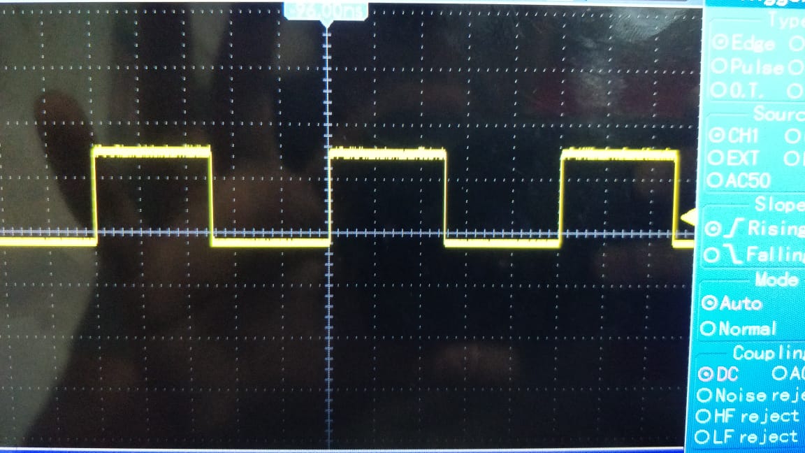
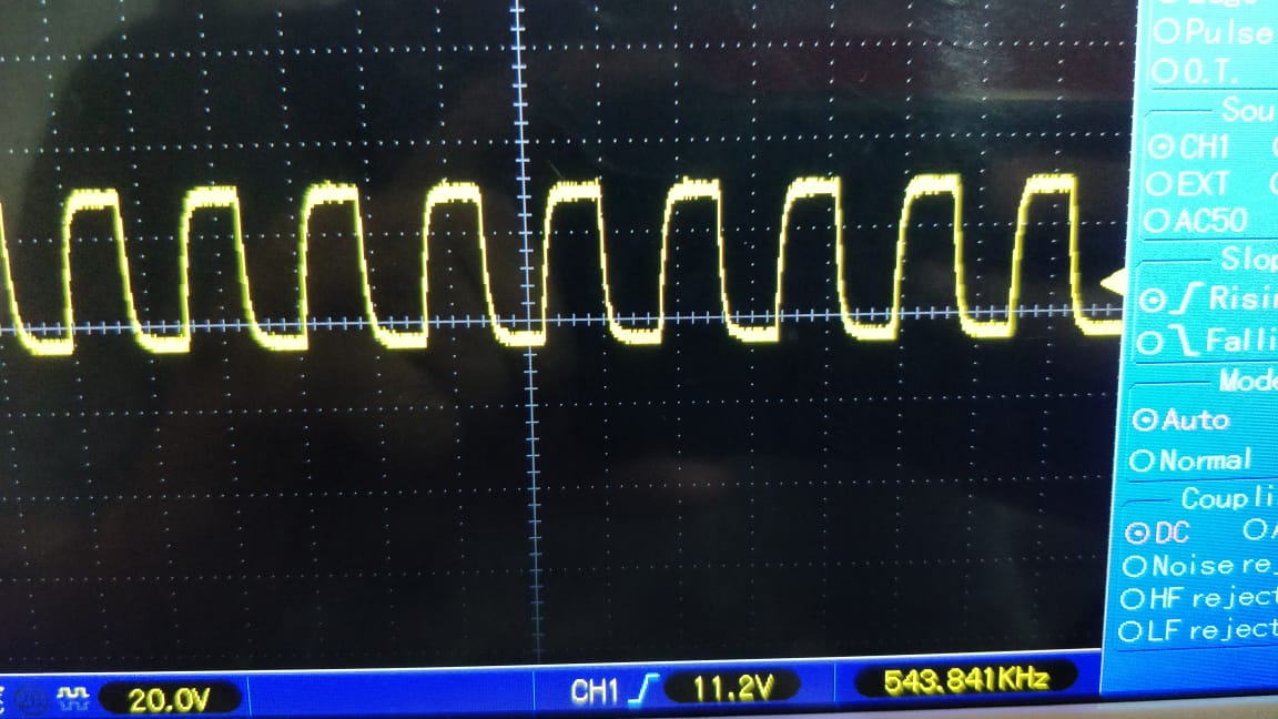
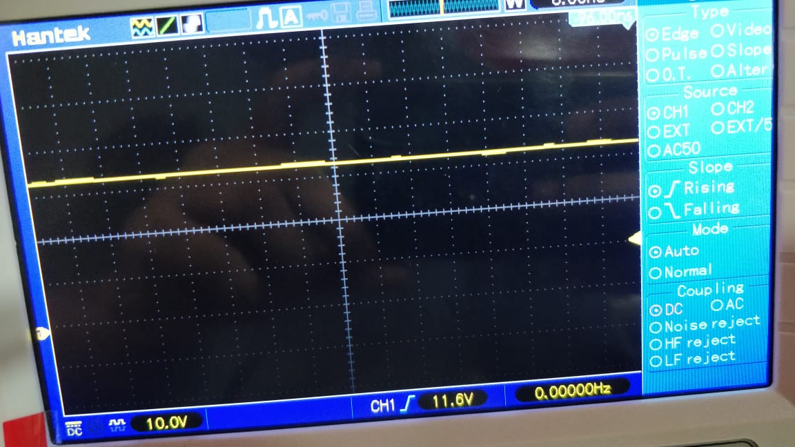
Moreover, whenever I try to connect the clock (MCASP1_ACLKR (Bit Clock) - P9_42) with my oscilloscope, I don't see any pulses. Looks like there is no proper clock signal on this pin. What can I do to debug, and fix this?
Any ideas?
Parag
Tool/software: Linux
I am trying to interface an I2S microphone (https://www.adafruit.com/product/3421) with BeagleBone Black. I followed the article (http://www.ti.com/lit/an/sprac97/sprac97.pdf), and able to update the device tree, and the Linux kernel as suggested in the article.
The I2S component (for microphone) of the device tree is included as a dtsi in the main device tree source. The content of the dtsi is as below
&am33xx_pinmux {
        mcasp1_pins: mcasp1_pins {
             pinctrl-single,pins = <
                /* sink must enable receivers */
                0x1a0 0x23
                /* P9_42 mcasp1_aclkx - bit clock */
                0x1a4 0x23
                /* P9_27 mcasp1_fsx - frame sync */
                0x1a8 0x23
                /* P9_41 mcasp1_axr0 - i2s input */
             >;
        };
};

&mcasp1 {
        #sound-dai-cells = <0>;
        pinctrl-names = "default";
        pinctrl-0 = <&mcasp1_pins>;
        status = "okay";
        op-mode = <0>;
        tdm-slots = <2>;
        num-serializer = <4>;
        serial-dir = < /* 1 TX 2 RX 0 unused */
                2 0 0 0
                >;
        rx-num-evt = <1>;
        tx-num-evt = <1>;
};

/ {
        pcm5102a: pcm5102a {
                #sound-dai-cells = <0>;
                compatible = "ti,pcm5102a";
                status = "okay";
        };

        sound1: sound@1 {
                compatible = "simple-audio-card";
                simple-audio-card,name = "PCM5102a";
                simple-audio-card,format = "i2s";
                simple-audio-card,bitclock-master = <&sound1_master>;
                simple-audio-card,frame-master = <&sound1_master>;
                simple-audio-card,bitclock-inversion;

                simple-audio-card,cpu {
                        sound-dai = <&mcasp1>;
                };

                sound1_master: simple-audio-card,codec {
                #sound-dai-cells = <0>;
                sound-dai = <&pcm5102a>;
                clocks = <&mcasp1_fck>;
                clock-names = "mclk";
                };
        };
};


I have also compiled the kernel with a new driver pcm5102 as suggested in the document. Finally, I see the driver listed in the output of the arecord command.
root@arm:/sys/class/gpio# arecord -l
**** List of CAPTURE Hardware Devices ****
card 0: PCM5102a [PCM5102a], device 0: davinci-mcasp.0-pcm5102a-hifi pcm5102a-hifi-0 []
  Subdevices: 1/1
  Subdevice #0: subdevice #0
However whenever I try to record audio, I am not getting any audio data. The audio file is formed, but the file size is always 44 bytes irrespective of how long I try to record audio for. Clearly no data is there in the file.
Recording using arecord command gives error as below
arecord -d 10 -Dhw:0,0 -f dat audio.wav
Recording WAVE 'audio.wav' : Signed 16 bit Little Endian, Rate 48000 Hz, Stereo
arecord: pcm_read:2032: read error: Input/output error
Moreover, whenever I try to connect the clock (MCASP1_ACLKR (Bit Clock) - P9_42) with my oscilloscope, I don't see any pulses. Looks like there is no proper clock signal on this pin. What can I do to debug, and fix this?
Any ideas?
Parag