This thread has been locked.

If you have a related question, please click the "Ask a related question" button in the top right corner. The newly created question will be automatically linked to this question.

CCS/TIDEP-0100: AM5708 DDR init HW-Leveling Timeout

Part Number: TIDEP-0100
Other Parts Discussed in Thread: AM5708

Tool/software: Code Composer Studio

CortexA15_0: GEL Output: --->>> DDR3L Initialization is in progress ... <<<---
CortexA15_0: GEL Output: DDR DPLL clock config for 400MHz is in progress...
CortexA15_0: GEL Output: DDR DPLL already locked, now unlocking....
CortexA15_0: GEL Output: DDR DPLL clock config for 400MHz is in DONE!
CortexA15_0: GEL Output: Launch full leveling
CortexA15_0: GEL Output: ERROR: HW-Leveling time-out
CortexA15_0: GEL Output: --->>> DDR3 Initialization is DONE! <<<---

Memory window shows all 0x0 starting at address 0x80000000

Could you please check the settings in the attached EMIF Config file.

Using Micron MT41K256M16TW-107 XIT:P

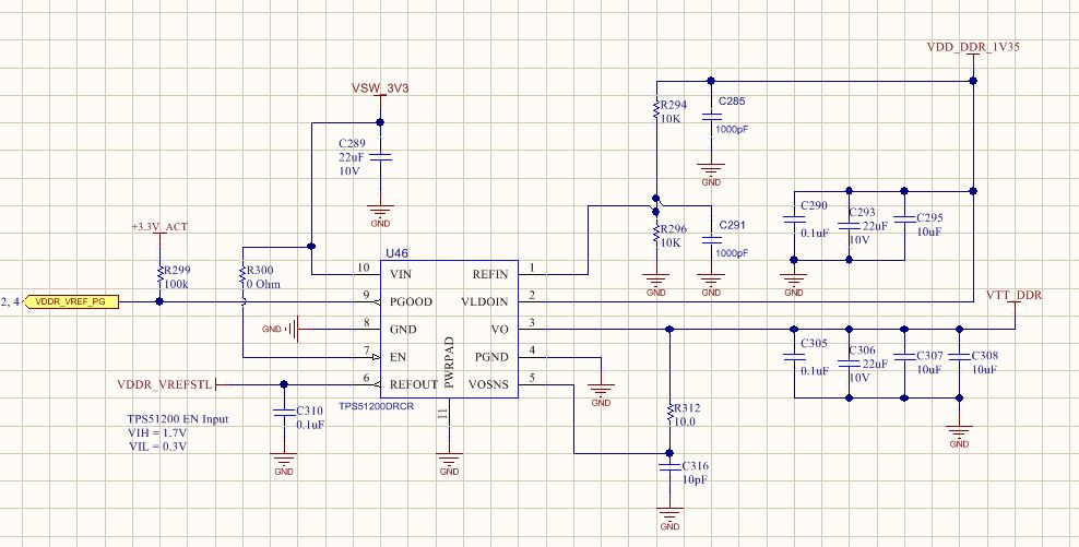
Attaching EMIF config file, and schematic page.

Thanks

AM5708-ddr.pdf

EMIF_RegisterConfiguration-2-10-2019.zip

  • AM571x_ddr_config_rf_500404.gelDo you require any additional information?  Also attaching the .gel file I'm using to initialize the DDR interface (AM5708 - 400MHz).

    Thanks

  • RD, a few questions:
    -can you attach the modified GEL file based on the EMIF tool output?
    -confirm that you are using a 19.2MHz input system clock?
    -Have you checked board voltages, especially VDDR_VREFSTL and VTT_DDR

    Regards,
    james
  • Hi James,
    I attached the modified .gelfile this morning in the previous post (AM571x_ddr_config_rf_500404.gel).
    Correct 19.2MHz input system clock.
    Yes, board voltages have been checked,including sequencing.

    I'm also able to run this script hotmenu AM570x_DDR3L_400MHz (you'll see it in the gel file) and I see the DDR_CLK change to 400MHz. Same with AM571x_DDR3_666MHz. I see the clock change to 666MHz.
    Hardware leveling error appears in both cases.
    Output: ERROR: HW-Leveling time-out
    All memory locations starting at Address 0x8000000 show value 0x00000000, and unable to change any values.

    Thanks
  • Sorry, i missed the attached GEL earlier.  

    I looked at your GEL and it looks like you are using AM570x_DDR3L_400MHz_Config() function to initialize the DDR.  Your DDR EMIF tool shows ECC disabled, but this function call shows ECC enabled:

    EMIF_Config(SOC_EMIF1_CONF_REGS_BASE,

    HW_LEVELING_ENABLED,

    ENABLE_ECC);

    Can you try disabling that and try again.  It may be causing an error because it is trying to perform h/w leveling on the ECC memory which isn't present.

    REgards,

    James

  • Hi James,
    There's a #define at the top of the file that disables ECC right?
    #define ENABLE_ECC (0)
    or is it enabled again somehow?

    Thanks
  • You are correct. I got mislead by the name of the define.

    I looked through your GEL, and i don't readily see any issues with the configuration you copied over from the tool. I have a couple more questions:

    -Did you actually measure the DDR clock with a scope on your board. The reason i ask is that the default GEL files i think assume a system input clock of 20MHz. I did a quick look and i don't think they have any provisions to change to 19.2MHz without some modifications. Did you also make changes to AM571x_prcm_config.gel? If you did, also attach that file
    -Can you also try running the GEL with just the default AM571x_CM_DDRIO_Config() instead of the one you modified from the EMIF tool.
    -I don't see the VTT regulator in the schematic snapshot you sent me. Just double check the VREF is properly connected from there and that VTT and VREF voltage values are valid during the leveling.

    Regards,
    James
  • Hi James,

    My answers below:

    - Did you actually measure the DDR clock with a scope on your board. The reason i ask is that the default GEL files i think assume a system input clock of 20MHz. I did a quick look and i don't think they have any provisions to change to 19.2MHz without some modifications.
    I will have to confirm the exact speed on Monday.

    - Did you also make changes to AM571x_prcm_config.gel? If you did, also attach that file.
    I did not make changes to AM571x_prcm_config.gel.  Please let me know what I need to change.

    - Can you also try running the GEL with just the default AM571x_CM_DDRIO_Config() instead of the one you modified from the EMIF tool.
    Will do.

    -I don't see the VTT regulator in the schematic snapshot you sent me. Just double check the VREF is properly connected from there and that VTT and VREF voltage values are valid during the leveling.
    I have checked this, and they look good, including the sequencing.

    On a related note, I found a difference in how the DDR_CKE pin is wired up, between the AM5708 ref design and the DRA71x ref design.
    See Page 8 pf both .PDFs.

    DRA71x ref design (has a 4.7K pulldown, and does not terminate to VTT):
    http://www.ti.com/lit/df/sprr281b/sprr281b.pdf

    AM5708 ref design (no pulldown, terminates to VTT):
    http://www.ti.com/lit/df/tidrts1/tidrts1.pdf

     Thanks

    RD

  • Hi James,
    It does look like the software is expecting a 20MHz system clock.  The 400MHz DDR script ends up being 384MHz and the 666 script ends up being 639MHz on the scope.
    I can change the crystal to a 20MHz.


    Some good news (even with the 19.2 crystal).
    DDR access seems to be fine with the 666 script, using the default config gel file or the new spreadsheet specific gel file!
    We can proceed with 666 for now until we figure out what's not set right in the 400 script.  This is the speed we would eventually like to run the interface at.

    With regard to the 666 script, should I continue to run it via the new custom .gel file?
    The reason I ask is it has these 2 new set of AM570x values that didn't exist in the default AM571x_ddr_config.gel

    static void AM570x_set_lisa_maps()
    {
    /* MA_LISA_MAP_i */
    HW_WR_REG32(SOC_MA_MPU_CONF_REGS_BASE + LISA_MAP_0, 0x00000000U);
    HW_WR_REG32(SOC_MA_MPU_CONF_REGS_BASE + LISA_MAP_1, 0x00000000U);
    HW_WR_REG32(SOC_MA_MPU_CONF_REGS_BASE + LISA_MAP_2, 0x80600100U);
    HW_WR_REG32(SOC_MA_MPU_CONF_REGS_BASE + LISA_MAP_3, 0xFF020100U);
    /* DMM_LISA_MAP_i */
    HW_WR_REG32(SOC_DMM_CONF_REGS_BASE + LISA_MAP_0, 0x00000000U);
    HW_WR_REG32(SOC_DMM_CONF_REGS_BASE + LISA_MAP_1, 0x00000000U);
    HW_WR_REG32(SOC_DMM_CONF_REGS_BASE + LISA_MAP_2, 0x80600100U);
    HW_WR_REG32(SOC_DMM_CONF_REGS_BASE + LISA_MAP_3, 0xFF020100U);
    }

    static void AM570x_CM_DDRIO_Config()
    {
    HW_WR_REG32(SOC_CKGEN_CM_CORE_AON_BASE + CM_DLL_CTRL, 0);

    HW_WR_REG32(SOC_CTRL_MODULE_CORE_CORE_PAD_REGISTERS_BASE +
    CTRL_CORE_CONTROL_DDRCACH1_0,
    0x80808080U);
    HW_WR_REG32(SOC_CTRL_MODULE_CORE_CORE_PAD_REGISTERS_BASE +
    CTRL_CORE_CONTROL_DDRCH1_0,
    0x40404040U);
    HW_WR_REG32(SOC_CTRL_MODULE_CORE_CORE_PAD_REGISTERS_BASE +
    CTRL_CORE_CONTROL_DDRCH1_1,
    0x40404040U);
    HW_WR_REG32(SOC_CTRL_MODULE_CORE_CORE_PAD_REGISTERS_BASE +
    CTRL_CORE_CONTROL_DDRCH1_2,
    0x00404000U);
    HW_WR_REG32(SOC_CTRL_MODULE_CORE_CORE_PAD_REGISTERS_BASE +
    CTRL_CORE_CONTROL_DDRIO_0,
    0x00094A40U);
    HW_WR_REG32(SOC_CTRL_MODULE_WKUP_CORE_REGISTERS_BASE +
    CTRL_WKUP_EMIF1_SDRAM_CONFIG_EXT,
    0x0000C123U);


    }

    Thanks.

  • Your scope observations confirmed my suspicions. You can either change your crystal to 20MHz, or change the GELs to accomodate 19.2MHz crystal. If you have no reason for 19.2MHz specifically, then i would recommend changing the crystal. Even though both input frequencies are supported, most of our EVMs have 20MHz crystal, so there will be more seemless support for this in the software.

    As for the GEL functions, i would stick with everything that the EMIF tool produces. The tool should be outputting optimized configuration for your design. If you still see issues, let us know.

    Regards,
    James